Hey, folks! Welcome back to our series on hardline water-cooling! Previously, we covered:
- Bending and Preparing PETG and Acrylic Tubing
- Working with Carbon Fibre and Brass Tubing
- Using Borosilicate Glass Tubes
This time, however, we're stepping backwards a bit and having a closer look at how exactly you plan a hardline loop in the first place.
It's quite a common question that pops up alongside the subject of hardline tubing, because from the outset it does seem like quite a task. Not being able to just put tubes in willy-nilly and have it all work out can make the subject quite daunting, particularly for newcomers to water-cooling. To that end, we're going to have a look at some of the methods used to both approximate tubing routes and ensure you don't get lost along the way.
CAD
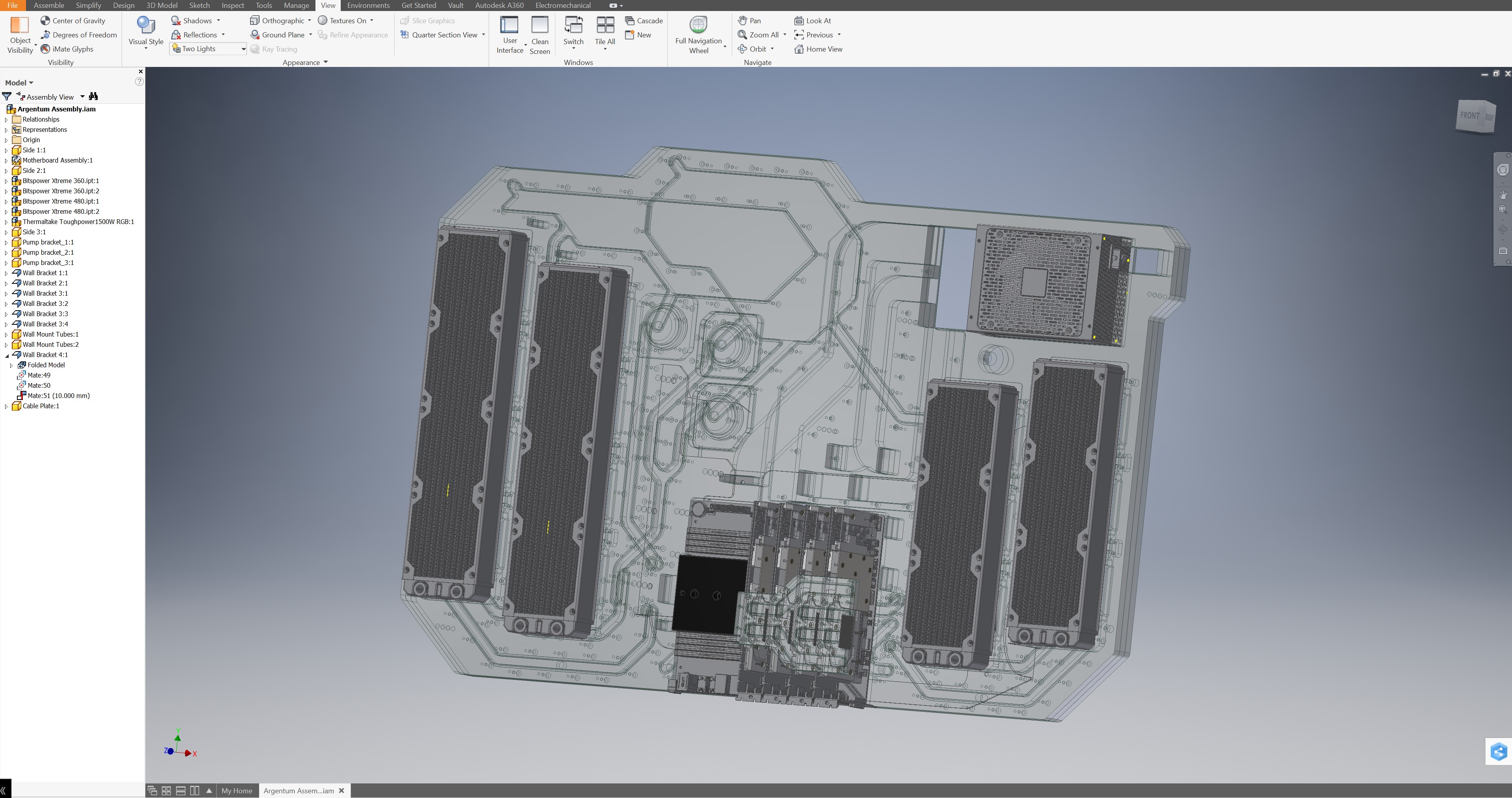
Quite often the first question people ask me is how I approach things for my own projects. For me, most of the time it comes down to Computer Aided Design, or CAD. Whilst it's definitely one of the most intensive ways to plan a water-cooling loop, I find it offers a huge amount of flexibility that more traditional methods simply can't hope to match. The main reason for this is that if you model a loop in a CAD package (I use Autodesk Fusion 360 now, which is free for non-commercial purposes and enthusiasts), you can take into account custom parts very easily.
I like to design water blocks and reservoirs that will later be machined from raw stock, and to make these you need a CAD model first. It follows that if you want to know where to place all the relevant ports and potential tubing routes, planning the whole loop in CAD actually makes a lot of sense. Usually, I will model all the components myself based on the physical objects, but if manufacturers are willing to supply accurate 3D models I will use those too. This means I can be confident that either the measurements are correct, or if something is wrong that I can troubleshoot it.


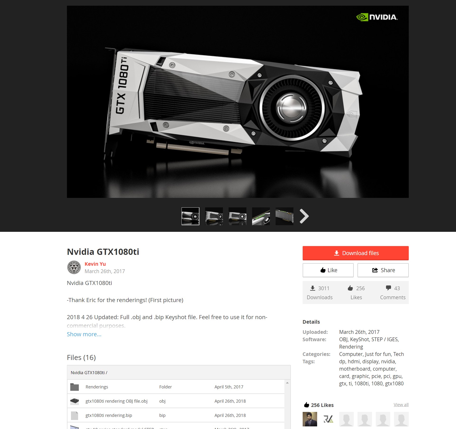
That's the hard way. It's not hard because it's difficult; it's just slow. There is a better way for quickly doing this, and that's to find freely available models online from sites such as GrabCAD. There's a colossal database of parts modelled by community members and shared, ranging from highly detailed parts to rough placeholders. Simply download the parts that fit your hardware configuration closest and plan away.
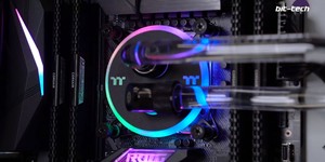
Aside from being able to include custom parts in a plan, CAD allows you to render your creation and visualise it - great if you're stuck as to which colour combination you wanted to try. Whilst it takes some time to get used to if you don't have prior experience, I would wholeheartedly push that it's worth the effort. For rendering, I like to use Cycles within Blender. It's free, open source, and very capable, the only issue being it doesn't interface with CAD packages natively (you have to import models and do everything manually). Fusion 360 has a capable rendering engine built in, however, so you can get some usable (and sometimes very impressive) results straight off the bat.


Exactly how to use CAD is a bit of a loaded question, though, because it differs from app to app. In general, though, you want to rough out your layout with your parts, assemble fittings into place, and then use the measuring tools to figure out tubing sizes. I use paths drawn from fitting to fitting to simulate the tubing runs, and this is quite a popular method, as you get a real sense of what the layout will look like. Just be sure to use values for your bends that match closely to real life; if you're too optimistic about making bends tight then you could be in for a rough ride later when you make the real thing.
RELATED ARTICLES


MSI MPG Velox 100R Chassis Review
October 14 2021 | 15:04

Want to comment? Please log in.