The Board

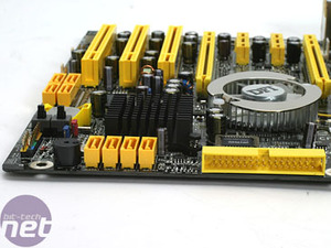
Interestingly, DFI has opted to actively cool ATI's RD580 north bridge. This is slightly different to the small passively cooled heatsink on the ASUS A8R32-MVP. The fan on the CFX3200-DR is a familiar one, as the company has used it since its DFI LANParty nF4-series motherboards. It's temperature controlled and the speed thresholds can be adjusted in the BIOS.
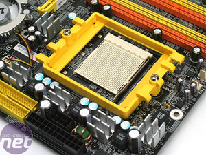
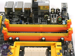
The area around the CPU socket looks to be reasonably problem free. In a rather typical fashion, DFI has heatsinked the PWM controllers that supply voltage to the CPU, and there is also a heatsink on the PWM next to the memory slots. Rather than being stuck on with adhesive or thermal tape, DFI has chosen to attach the heatsinks on with small clamps that are soldered through the motherboard - this stops them falling off during transit while also giving a firm and consistent contact between the PWM and the heatsink covering it, and assuming there is regular TIM under there, this should produce superior performance to either adhesive or tape.


Rather than the standard four-pin ATX 12V connector, DFI has opted for the eight-pin variety that provides cleaner power to the CPU. It is still possible to run this motherboard with a four-pin connector though, as the new eight-pin standard is backwards compatible with the older four-pin version. Some motherboards with an eight-pin ATX 12V connector refused to work with a four-pin plug connected, but this board fired up fine with the older four-pin plug connected. The manual also makes reference to it working, too.
There is one other power connector on the board too - it's located next to the top of the primary PCI-Express x16 connector. The connector is a floppy type four-pin socket that DFI recommend using when running two video cards in CrossFire. It's not in an ideal position, but we believe that its position is required to ensure that the power supplied to the video cards is as clean as possible. There would also be issues with trace lengths and the heat emitted by those traces if the socket was moved to a more convenient location.


Interestingly, the two IDE ports are mounted in a traditional fashion, while the floppy port is rotated 90 degrees to allow for improved cable management. It seems a bit strange for DFI to rotate the floppy connector, when very few people use them these days. In our opinion, it would have made more sense to rotate at least one of the IDE connectors instead.

MSI MPG Velox 100R Chassis Review
October 14 2021 | 15:04


Want to comment? Please log in.