Space: the final frontier. This is the limitation of having a small workshop, a limitation that has a habit of rearing its ugly head at the worst of times and one which almost everybody is accustomed to in one way or another. In my instance, I have a rather bad case of TAS (tool acquisition syndrome) which has resulted in my workshop steadily getting ever more crammed; one only has to go back and watch some of the earlier videos on our YouTube channel to observe how things have steadily been snaking around the entire shop. To that end, one thing has bugged me for quite a while: lighting.
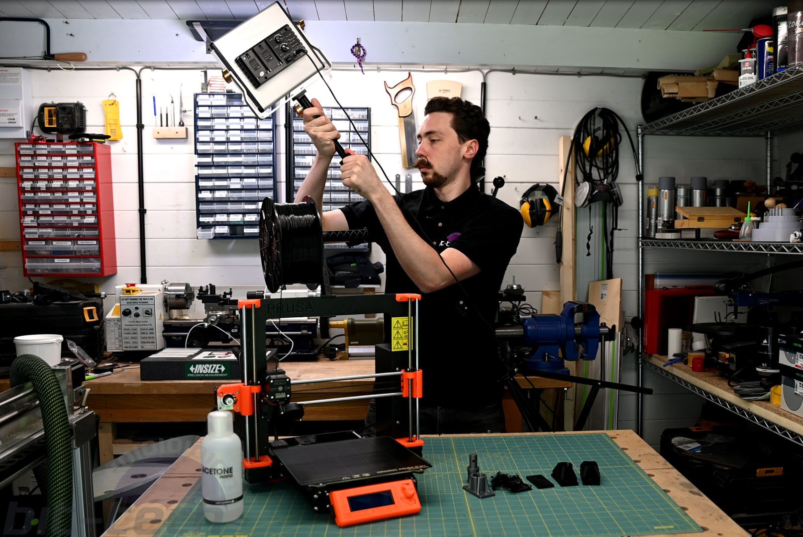
Lighting is crucial for video and photography, but it typically takes up a lot of room. Until very recently, I had to make use of tripods to hold LED panels to provide continuous lighting for high frame rate footage. In a larger space these would be fine, but in my workshop there really isn't room for them. Not only are they simply a pain to manoeuvre around, but they're frankly dangerous too; I've certainly tripped on them a couple times before.
To that end, I thought it would be a fun 3D printing exercise to come up with a solution for this, to be able to do away with tripods for static lighting and free up that space. 3D printing is ideal for solving these sorts of real-world problems, as sometimes there simply isn't an existing product that does the job quite how one wants, or if there is then the solution might be expensive or challenging to source.
What's the Plan?
Considering my space, I realised that the biggest weakness of my workshop could be a real boon here. Having little space means I'm always within arm's reach of a wall or the ceiling, which makes brackets ideal. The Neewer lights use a simple method to attach to the tops of the tripods. The light frames feature a socket, which is placed over a metal top on the tripod, and you then tighten a set screw on the side to lock it in place. This is effective, but I'd rather not be screwing and unscrewing things all the time. A design in which the light can simply click into place in a number of locations sounded a better deal - think of how action cams can just slide into holders mounted wherever you wish.

One thing I love about 3D printing is the ability to print mechanisms directly into the structure of an object itself. Using the example of the action cams, the injection moulded holders are springy so require no extra parts to function, keeping things super simple. I figured that would be perfect here too - have one part with a basic mechanism and the other with the corresponding shape. With that in mind, I set to work coming up with a concept.

This is what I arrived at. It's a straightforward, two-piece mechanism with a male and female connector. The male connector fits into the socket on the lighting frames and is secured with the default set screw, the female connector is then placed wherever you wish. The female connector features a split socket; two of the prongs have an internal lip on them and are flexible, while the other two are smooth on the inside and are braced - these provide support whilst the others provide the clipping action. This means a female connector can be placed on, say, the wall or ceiling, and you simply push the light into it, it should click into place and be held firm.
Iterative Design Process
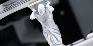
With the first design ready, I exported the .stl from Fusion 360, popped into Prusa Slicer and prepped it for printing in Silver PLA, the default material that came with my printer. I just wanted to test whether the system would work at all, so choosing a reliable print material made sense. Three hours later I had a fully functional part! This bit still blows my mind a bit, the process of going from idea to working prototype is so fast thanks to this technology.

Impressively, the prototype functioned rather well! However, there were some issues. The main one was simply strength. I clearly didn't beef the braces enough, as when I placed a light in and held it sideways, the part flexed far more than I was comfortable with. The other main issue lay with the material itself: PLA is great to print, but it does have limitations in that it's not very flexible and also degrades over time under stress, heat, and moisture.

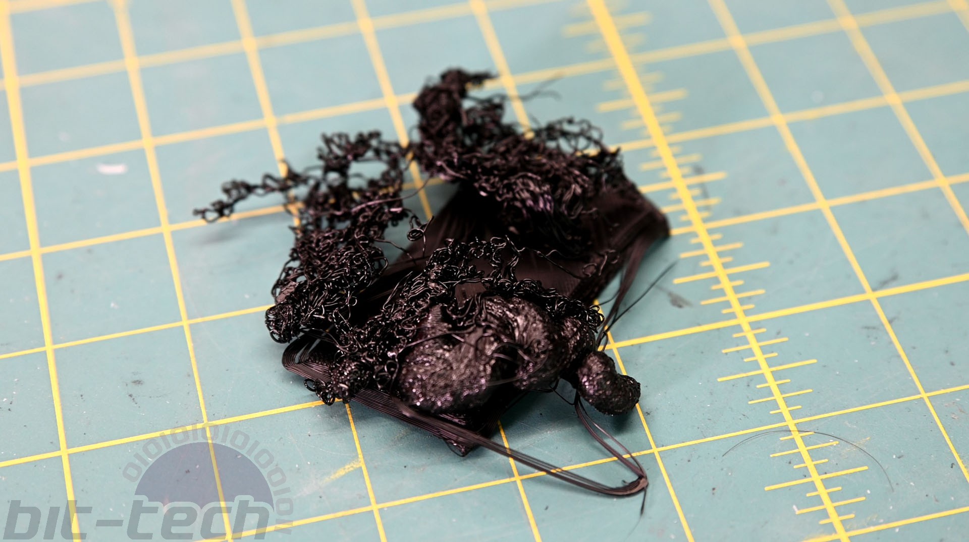
MKII was exactly the same part as MKI but this time printed in ABS. I figured that it would be worth exploring what changes the material would make to the mechanism before choosing to alter things much. Rather amazingly, it printed perfectly straight off the bat, but clearly my design was lacking, as it snapped the moment a family member flexed it a little. I then went and beefed it up a bit, added some larger supports, and thickened the walls of the mechanism. I also decided to try printing with a high infill to see how it would change. Unfortunately, it sort of... killed it. In fact, this print was just a pure disaster: The ABS didn't adhere to the bed properly at all and just became a big ball of messy string.
Not perturbed, I tried again with a freshly cleaned nozzle and bed, same settings as before (80 percent infill). This was more successful at least, but I still cancelled the print thanks to excessive warping. I decided that perhaps that infill level was simply too high for this machine without a heated enclosure and whatnot. So I tweaked the model a little more to make up for the lower infill, then printed again, this time using 30 percent. Huzzah! We got a proper, successful print this time! However, whilst the print was pretty good, it became evident that my alterations weren't so desirable all over.


A side effect of beefing up the whole model was that it became stiffer, thus rendering the mechanism very difficult to use. Sure, it worked, but I figured I'd be more likely to break it again given how much force was required to insert/remove the light. Taking cues from that, I came up with a few more alterations for MKIV. MKIII had a crucial flaw in its design: I had left the prongs round at the base, which meant that innately the shape would be hard to flex - think Gaussian curvature and all that. For MKIV I made the walls of the prongs flat instead to make them more flexible, and this meant I could thicken them a bit more too. I then also reduced the interior lip a little so that they wouldn't have to expand as much to accommodate the male connector.


Another three hours later and the MKIV was working perfectly. The part was more flexible despite having thicker walls, and the reduced lip meant that the lights could be inserted/removed easily with a satisfying click, without fear of them falling out randomly one day. I then proceeded to print off another 10 mounts overnight, and placed them all over the workshop by the most commonly used areas.
If you use these or similar lights for things yourself and would like to have a go printing them out (or adapting to suit your own kit/space) then you're in luck, as I've uploaded the 3D files to GrabCAD!
You can find the 3D files here!


MSI MPG Velox 100R Chassis Review
October 14 2021 | 15:04

Want to comment? Please log in.