
Setting up
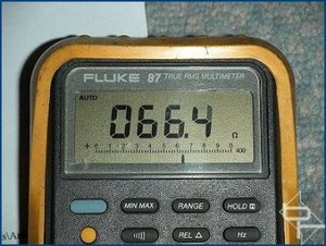
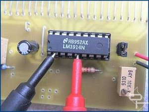
Setting up is simple but does involve a degree of trial and error. As before, I have included some resistance settings for VR2 and VR3 to give a reasonable starting point. Remember to set these measurements with the power disconnected from the circuit.
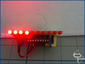
It helps to have the meter in BAR mode when setting up. With power connected and the HDD LED connection from the motherboard plugged in to the meter board, adjust VR3 so all the meter LEDs are just off. Then give the HDD something to do, I copied the pak0.pk3 file from the Quake 3 CD to my HDD. This file is 468MB and is big enough to allow sufficient time and constant HDD activity to set VR2. You can use any large file so long as it takes enough time to allow the setting of VR2. Whilst the file is copying adjust VR2 so all the LEDs are just fully lit.
Go back and check the VR3 setting and if needed readjust. If VR3 is readjusted then VR2 will also require tweaking. Keep repeating this fine tuning of the controls until no more adjustment is needed. The idea is to have no LEDs lit with no HDD activity and all LEDs lit, or the top LED in the case of using DOT mode, with constant drive activity. The in-between bits will look after themselves!
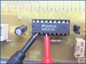
Adjust VR3 so all the LEDs are just extinguished.
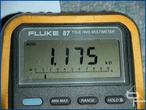
VR2 is adjusted so that all LEDs are lit during constant drive activity.
The meter is an indication of the level of HDD activity, which can be influenced by operating system file caching, and as such, is somewhat subjective in how the display is interpreted. The component values used in the circuit produce excellent results with the motherboard/hard drive combinations tested but due to design variations between motherboards from different manufacturers, experimenting with the value of C2 may produce better/worse results. Values between 10uF - 100uF should be suitable.
The same comments about experimenting with the circuit made in the sister article here also apply to this design.
Any questions or comments about this circuit can be raised on the forum here.
Setting up is simple but does involve a degree of trial and error. As before, I have included some resistance settings for VR2 and VR3 to give a reasonable starting point. Remember to set these measurements with the power disconnected from the circuit.
It helps to have the meter in BAR mode when setting up. With power connected and the HDD LED connection from the motherboard plugged in to the meter board, adjust VR3 so all the meter LEDs are just off. Then give the HDD something to do, I copied the pak0.pk3 file from the Quake 3 CD to my HDD. This file is 468MB and is big enough to allow sufficient time and constant HDD activity to set VR2. You can use any large file so long as it takes enough time to allow the setting of VR2. Whilst the file is copying adjust VR2 so all the LEDs are just fully lit.
Go back and check the VR3 setting and if needed readjust. If VR3 is readjusted then VR2 will also require tweaking. Keep repeating this fine tuning of the controls until no more adjustment is needed. The idea is to have no LEDs lit with no HDD activity and all LEDs lit, or the top LED in the case of using DOT mode, with constant drive activity. The in-between bits will look after themselves!
Adjust VR3 so all the LEDs are just extinguished.
VR2 is adjusted so that all LEDs are lit during constant drive activity.
The meter is an indication of the level of HDD activity, which can be influenced by operating system file caching, and as such, is somewhat subjective in how the display is interpreted. The component values used in the circuit produce excellent results with the motherboard/hard drive combinations tested but due to design variations between motherboards from different manufacturers, experimenting with the value of C2 may produce better/worse results. Values between 10uF - 100uF should be suitable.
The same comments about experimenting with the circuit made in the sister article here also apply to this design.
Any questions or comments about this circuit can be raised on the forum here.
RELATED ARTICLES


MSI MPG Velox 100R Chassis Review
October 14 2021 | 15:04

Want to comment? Please log in.