
Building the circuit.
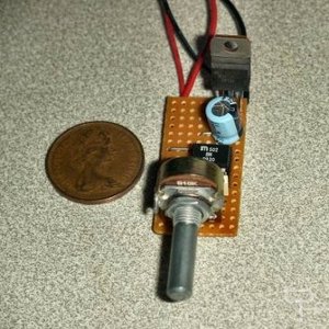
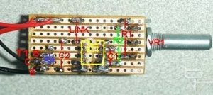
Here is an example of the built circuit on a small piece of stripboard. The 2p coin gives an indication of size. I have not included the diode D1 in this example.
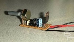
Side view.
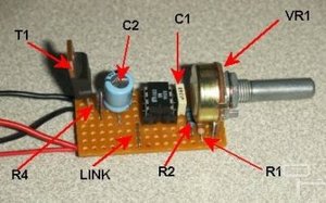
General layout of components.
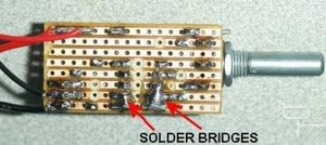
Under side of the board showing the breaks in the stripboard tracks. Note the use of solder bridges to link leads on IC1.
Underside of the board showing component locations.
Component List: figures in brackets are Rapid Electronics stock codes.
IC1 = MIC502BN (82-4026)
T1 = TIP122 (81-0172)
D1 = 1N4001 (47-3420)
R1 = 10K (62-2146)
R2 = 15K (62-2154)
R4 = 270R (62-2070)
VR1 = 10K Linear (65-0715)
VR2 = 47K Linear (65-0725)
Thermistor = (61-0515)
C1 = 0.1uF (10-3220)
C2 = 220uF 25V (11-0265)
Here is an example of the built circuit on a small piece of stripboard. The 2p coin gives an indication of size. I have not included the diode D1 in this example.
Side view.
General layout of components.
Under side of the board showing the breaks in the stripboard tracks. Note the use of solder bridges to link leads on IC1.
Underside of the board showing component locations.
Component List: figures in brackets are Rapid Electronics stock codes.
IC1 = MIC502BN (82-4026)
T1 = TIP122 (81-0172)
D1 = 1N4001 (47-3420)
R1 = 10K (62-2146)
R2 = 15K (62-2154)
R4 = 270R (62-2070)
VR1 = 10K Linear (65-0715)
VR2 = 47K Linear (65-0725)
Thermistor = (61-0515)
C1 = 0.1uF (10-3220)
C2 = 220uF 25V (11-0265)


MSI MPG Velox 100R Chassis Review
October 14 2021 | 15:04

Want to comment? Please log in.