
The Molex Connector
Molex connectors are the electromodder's best friend. They provide stable, accurate power on tap wherever you need it inside, or even a little outside your case. If you're reading this you'll probably have pushed in and pulled out a good few molex connectors in your time, yet most people don't know what those 4 wires are. All that you need to know about a molex is what voltage each of the lines are, take a look at this diagram:
You may wonder why there are two 0V lines, surely one is enough, right? Well, one 0V line is enough for our purposes since every circuit will share this common 0V connection. The complex circuits inside things like hard-drives are a different matter though, providing different 'routes' to 0V can help keep interference low and power more stable when it comes to high frequency signals. We'll look more into the weird effects of high frequencies and inductance when we come onto building a pulse width modulator for controlling fans with in later parts. For now though, forget I said anything.
The First Project
Components are the building blocks of every circuit. We connect them together with wires or copper tracks to make circuits, but it's the components that do all the work. The first thing we're going to be making in this series is a simple LED light for your case which will use two of the most common components. This will take us through what a resistor does, what an LED does, how to calculate resistor values and how to read circuit diagrams... oh, and you'll get a pretty light at the end. What more could you want?
I'm pretty sure you'll have come across LEDs before: the average modders case probably has about a dozen of the things; many of you will also know that LED stands for Light Emitting Diode. They come in all shapes, size and colours, if you buy them fresh they might look something like this...
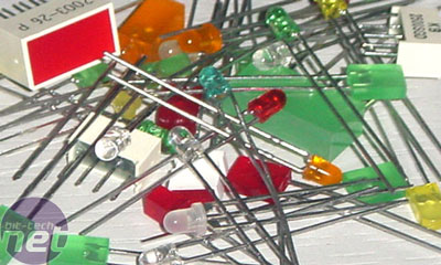
You may have noticed that one leg is shorter than the other and, if your eyes are good, that there is a flat-side to the base of the LEDs body. Being a Diode (albeit one that produced purty colours!), and LED will only permit current to flow in one direction. You might have discovered this when building your PC: basic stuff like your reset button (and elementary push-to-make switch) can be connected either way around, but your Power LED & Hard Drive LED will only light up when the positive and negative terminals are correctly matched.
This is why the legs are different lengths: the positive leg is always the longer of the two. If you connect an LED the wrong way round it won't kill it - it just wont produce any light.
So, from what we know about LEDs and molex connectors gives us this circuit diagram. The direction of the LED is indicated by the direction of the triangle, the negative short leg is always the point of the triangle:
Unfortunately it's not as easy as that, and that circuit diagram is a recipe for LED death. This is because LEDs have maximum 'forward voltage' limits (usually between 1.8V and 3.6V) and maximum current limits (usually between 10mA and 35mA). To take some of the voltage and limit the current to protect the LED we need to use a component called a resistor, which look like this:
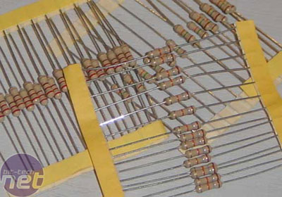
The resistor will absorb some of the voltage across it when we place it in series with the resistor. The amount of voltage it takes depends on how big it's resistance is which is measured in Ohms. To work out this value we need to use a formula derived from ohms law which looks like this:
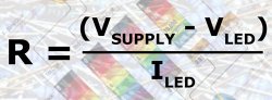
Scary, huh? Let's do an example using these LED specs:
LED Forward Voltage: 2.2V
LED Max Current: 25mA
Power Supply: 5V Molex
So, using that formula we'll take the LED Forward Voltage away from the Power Supply to give 5–2.2 = 2.8V. This is the voltage the resistor needs to take across it. Now we need to divide this by the Max Current – this is where most new comers go wrong. The formula expects the current to be in amps, but we've been given the current rating in milliamps. Now, 1 milliamp is one thousandth of an amp, so to convert from mA to A we need to divide by 1000. This gives us a value of 25/1000 = 0.025A. We can now divide 2.8/0.025 to give us the value of resistor needed! The answer is, drum roll please, 112Ohms. We can't actually use this value for reasons I'll go into in the next part when we'll be covering the practical implementation of the circuit in our rig but we'll pretend we can for now. Our final circuit diagram now looks like this:
If you were to use this circuit, your LED is ensured a bright and happy life. This is the diagram we'll be using in the next part of the guide to construct our case light.
Conclusion
That's all for this part folks. In the next part of the series we'll be using the circuit diagram we just worked out to make a working LED light for our case, looking at the practical side of the theory we've covered. If not all of what I've covered is sticking in your brain, don't worry about it. Electronics is far easier to learn by doing than by reading up on equations and diagrams. As the series progresses you should find yourself getting more of a 'feel' for it and getting confident enough to tackle more complex circuits.
Molex connectors are the electromodder's best friend. They provide stable, accurate power on tap wherever you need it inside, or even a little outside your case. If you're reading this you'll probably have pushed in and pulled out a good few molex connectors in your time, yet most people don't know what those 4 wires are. All that you need to know about a molex is what voltage each of the lines are, take a look at this diagram:
The First Project
Components are the building blocks of every circuit. We connect them together with wires or copper tracks to make circuits, but it's the components that do all the work. The first thing we're going to be making in this series is a simple LED light for your case which will use two of the most common components. This will take us through what a resistor does, what an LED does, how to calculate resistor values and how to read circuit diagrams... oh, and you'll get a pretty light at the end. What more could you want?
I'm pretty sure you'll have come across LEDs before: the average modders case probably has about a dozen of the things; many of you will also know that LED stands for Light Emitting Diode. They come in all shapes, size and colours, if you buy them fresh they might look something like this...
This is why the legs are different lengths: the positive leg is always the longer of the two. If you connect an LED the wrong way round it won't kill it - it just wont produce any light.
So, from what we know about LEDs and molex connectors gives us this circuit diagram. The direction of the LED is indicated by the direction of the triangle, the negative short leg is always the point of the triangle:
LED Forward Voltage: 2.2V
LED Max Current: 25mA
Power Supply: 5V Molex
So, using that formula we'll take the LED Forward Voltage away from the Power Supply to give 5–2.2 = 2.8V. This is the voltage the resistor needs to take across it. Now we need to divide this by the Max Current – this is where most new comers go wrong. The formula expects the current to be in amps, but we've been given the current rating in milliamps. Now, 1 milliamp is one thousandth of an amp, so to convert from mA to A we need to divide by 1000. This gives us a value of 25/1000 = 0.025A. We can now divide 2.8/0.025 to give us the value of resistor needed! The answer is, drum roll please, 112Ohms. We can't actually use this value for reasons I'll go into in the next part when we'll be covering the practical implementation of the circuit in our rig but we'll pretend we can for now. Our final circuit diagram now looks like this:
Conclusion
That's all for this part folks. In the next part of the series we'll be using the circuit diagram we just worked out to make a working LED light for our case, looking at the practical side of the theory we've covered. If not all of what I've covered is sticking in your brain, don't worry about it. Electronics is far easier to learn by doing than by reading up on equations and diagrams. As the series progresses you should find yourself getting more of a 'feel' for it and getting confident enough to tackle more complex circuits.


MSI MPG Velox 100R Chassis Review
October 14 2021 | 15:04

Want to comment? Please log in.