Board Layout (continued)
Cooling
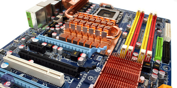
Gigabyte opts to separate the south bridge from the north bridge heatsink, and as such it's much larger than we're used to. This is because it has to remain low profile in order to allow graphics cards to sit above it. However, because Gigabyte uses only two plastic push-pins the heatsink rocks when you gently push down on either end – hardly a secure contact with a hot chipset.While the north bridge still uses the same push-pins, it's thankfully held down by four at the corners and covers both north bridge and NF200 chipset with one massive 'sink that measures 75mm x 80mm (yeah, when we said massive, we mean it). A single heatpipe snakes between the fins and then out towards the CPU power regulation components, which certainly helps to dissipate the heat a little more evenly. Although we didn't receive a retail box, there's no obvious additional placement to drop a fan onto it so maybe Gigabyte is intending to go it alone passively which could limit the board’s overclocking potential.
Sound and Ethernet
Like all Gigabyte boards worth having these days, we find it has the Realtek ALC889a codec which has previously performed extremely well in our RMAA 6.02 tests. Both Gigabit Ethernet sockets are now powered by Realtek chipsets as opposed to Marvell, but they are both still Physical Layer connected directly to the NF570 MCP south bridge.
Rear I/O
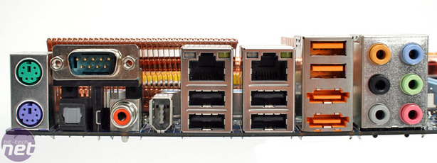
The Gigabyte rear I/O is far more feature packed than the XFX – in addition to the six USB 2.0 ports, 6-pin Firewire socket, two RJ45 Ethernet sockets, two PS/2 ports, six 3.5mm audio jacks and optical S/PDIF out, there is also the following:- Two eSATA ports
- Coaxial S/PDIF
- And a RS232 serial port

BIOS
Unfortunately when we tried to boot the board we were presented with a bad BIOS flash, and even though the board tried to automatically correct itself using its internal backup(s), it still wouldn’t boot. This is actually really disappointing because it's not like we can take the BIOS chip out of the board either since it is hard-soldered to the board. When we tried to enter the in-BIOS QFlash facility to manually correct it we were also unable to – eventually it just gave up and sat there non-POSTing with a blank screen.The only other option we have left with our sample is to return the board back to Gigabyte. While we’d be disappointed if this had happened with a retail board, as an early sample this can sometimes happens.

MSI MPG Velox 100R Chassis Review
October 14 2021 | 15:04


Want to comment? Please log in.