

Lights & Glue
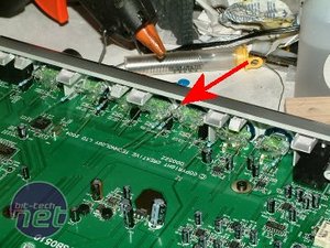
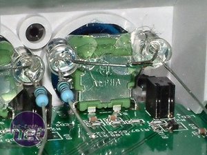
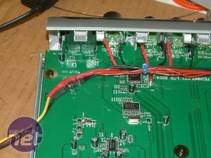
With the front fascia re-assembled, two blue LEDs were fitted behind each control - fourteen LEDs in total. The LEDs were mounted either side of each control using a hot glue gun. Each pair was wired in series with its own current limiting resistor. The second picture is a close-up of one pair of LEDs in place with their resistor.
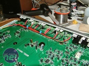
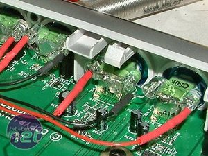
Wires were then soldered to the component leads and the joints insulated with heat shrink sleeving.
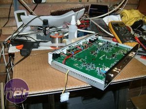
The wires were brought back to a common point and a standard power connector fitted to juice up the LEDs. The power connector cable was passed through a ventilation slot in the side of the chassis to facilitate connection to the system PSU.
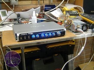
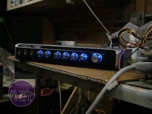
With the wiring completed, the I/O module was fully re-assembled and the back lighting tested.
Time to get baffled…

MSI MPG Velox 100R Chassis Review
October 14 2021 | 15:04


Want to comment? Please log in.