The Wiring


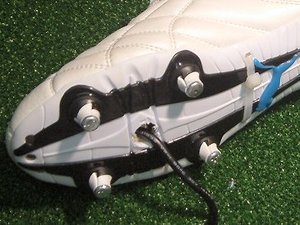
With the screw alignment verified, the boots were unscrewed from the base to allow further modifications to be inflicted on them. In the case of the right boot, the system PSU was to be installed. Firstly several holes were drilled in to the sole of the boot to accommodate the various cables etc.


The 12V output cable was fed through the front hole and the mains cable through the rear one.


The PSU block was then fully inserted inside the boot and retained in place using a nylon cable tie.


More holes were drilled through the base board for the boots’ cables to pass through. The boot was then reattached to the base.


Now for the left boot. This will house the system power switch. The switch is a small red push button.


Similarly to the right boot, various holes were drilled in the boot and the base to accommodate the wires. The boot was then screwed back on to the base.

MSI MPG Velox 100R Chassis Review
October 14 2021 | 15:04


Want to comment? Please log in.