Project N.V. by Hans Peder Sahl (p0Pe)
October 16, 2013 | 10:09
Companies: #aquacomputer #bit-tech #corsair
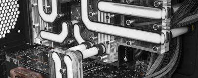
One of the more interesting challenges was that the motherboard block was built in such a way that the ports for it sat behind the first graphic card. This meant that I had to make a “bridge” from the main interconnect block, over the first graphic card, and then down to the motherboard block. This bridge had to be small since the graphic cards power connectors would interfere if it was too wide.
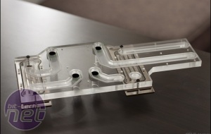
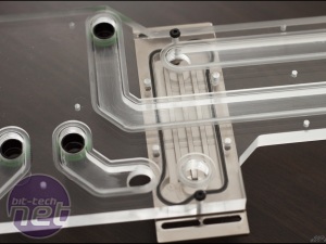
The first prototype that was made was almost perfect. I had to slightly correct a few measurements, and the there was one big mistake where I put a hole in a spot where there should not have been a hole! This is the danger of working in 3D programs where you constrain everything to be dependent on other things, sometimes stuff will happen that you do not notice. Luckily this was only a prototype, and I kind of expected that another one had to be made.
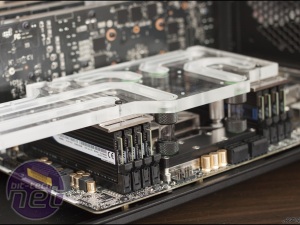
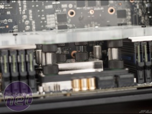
These pictures show how the interconnect block connects to the volt regulators and the CPU block via solid tubing. I was amazed at how hard it actually was to get these pushed down there, and a few times I was actually worried that I had broken the motherboard. If you have worked with solid tubing you should know that sometimes it can be hard to get the tube into the fitting. Now, multiply that by 4 and you should know what I mean.
Nate, who machined the designs for me, was also kind enough to make a video of the milling in action. This job apparently turned out to be one of the more demanding jobs for him as many of the parts had to be milled on both sides, and with a near zero tolerance factor.
Click to enlarge
The first prototype that was made was almost perfect. I had to slightly correct a few measurements, and the there was one big mistake where I put a hole in a spot where there should not have been a hole! This is the danger of working in 3D programs where you constrain everything to be dependent on other things, sometimes stuff will happen that you do not notice. Luckily this was only a prototype, and I kind of expected that another one had to be made.
Click to enlarge
These pictures show how the interconnect block connects to the volt regulators and the CPU block via solid tubing. I was amazed at how hard it actually was to get these pushed down there, and a few times I was actually worried that I had broken the motherboard. If you have worked with solid tubing you should know that sometimes it can be hard to get the tube into the fitting. Now, multiply that by 4 and you should know what I mean.
Click to play
Nate, who machined the designs for me, was also kind enough to make a video of the milling in action. This job apparently turned out to be one of the more demanding jobs for him as many of the parts had to be milled on both sides, and with a near zero tolerance factor.

MSI MPG Velox 100R Chassis Review
October 14 2021 | 15:04



Want to comment? Please log in.