
The Classic Knight Rider
This circuit uses 10 LEDs to produce the effect of a single LED continuously moving back and forth in a line. The circuit comprises of two main parts, a triangle wave oscillator and an LED bargraph. Looking at the circuit below, IC1 is a dual op-amp configured as an oscillator, the output of which is a triangle wave. The oscillators frequency can be varied by adjusting VR3. The triangle output is fed into IC2, an LM3914 10 segment LED bargraph. This chip is basically a voltmeter which lights a series of LEDs, the number of LEDs lit is proportional the the voltage fed into the chip. Since the input to the chip is a triangle, (continuously rising and falling voltage), the LEDs light sequentially giving rise to the "scanning" effect. The chip can operate in either of two modes, "DOT" or "BAR". In DOT mode only one LED is lit at a time. This produces the classic Knight rider effect. By linking points "A" and "B" on the circuit "BAR" mode is selected. In this mode the LEDs progressively light until all the LEDs are lit producing a "bar" of light.
The circuit is designed to operate from the PC's +12V supply. VR1 adjusts the zero or start point of the meter. VR2 adjusts the meters span or end point and VR3 sets the oscillator frequency and hence the speed of the effect. Basically VR1 and VR2 determine how the effect looks. I will cover the setting up procedure in more detail later.
Linking points "A" and "B" switches the display into "BAR" mode which changes the effect into a continuously "growing and shrinking" line of LEDs.
Parts List with order codes for UK and US suppliers
The PCB layout if using individual LEDs.
NOTE: The PCB foil pattern shown, (and for all board versions), is not to scale. Clicking on the picture will open a 4x sized version which should be printed out at 25% of original size. This ensures an accurate and sharp print out for PCB exposure. Paint programs such as Paint Shop Pro allow for such reductions when printing. Do not rescale the picture and then print it, have the printer do it during printing. Don't forget to fit the small link shown in red on the layout. Also note the position of R3 which has two possible positions. You can see the two unused holes between R3 and R4 on the layout.
Component layout - top view (left) and Track layout - Viewed from above (right)
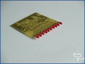
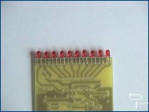
When assembling the components on the circuit board it is usually a good idea to fit the components with the least height first, working your way up to the tallest. It makes the board wobble less when trying to solder! For this project I recommend fitting the LEDs first as this will make aligning them accurately easier and will produce a nice even line of light. If your board has a decently flat edge then butting the LED base up to it will make it much easier to get all the LEDs in a straight line. The procedure to bend the LED legs to fit the board perfectly is discussed later under the 20 LED version.
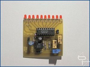
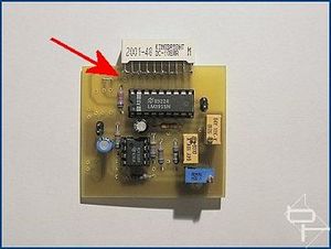
The finished board. The unused holes are to accommodate components used in the alternate versions yet to be described.
The PCB layout if using a single LED array.
When building this version I suggest fitting the LED bargraph last to make the board assembly easier. This board has one small link marked in red. Again note the position of R3.
Component layout - top view (left) and Track layout - Viewed from above (right)
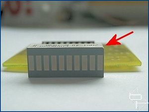
The bargraph has two rows of connection pins. A row of anodes and a row of cathodes. The bargraph I used had a bevelled corner, indicated by the red arrow below, to denote which row of pins were the anodes. If you use a different LED array check for correct polarity before soldering it to the board! The array is mounted by soldering the cathodes directly to the circuit board, unlike the anodes which are linked together and connected to PAD13 using wire. (See below).
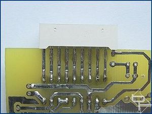
The finished board and a detail of how the anodes are linked together and connected to the board using pad13, indicated by the red arrow.
This circuit uses 10 LEDs to produce the effect of a single LED continuously moving back and forth in a line. The circuit comprises of two main parts, a triangle wave oscillator and an LED bargraph. Looking at the circuit below, IC1 is a dual op-amp configured as an oscillator, the output of which is a triangle wave. The oscillators frequency can be varied by adjusting VR3. The triangle output is fed into IC2, an LM3914 10 segment LED bargraph. This chip is basically a voltmeter which lights a series of LEDs, the number of LEDs lit is proportional the the voltage fed into the chip. Since the input to the chip is a triangle, (continuously rising and falling voltage), the LEDs light sequentially giving rise to the "scanning" effect. The chip can operate in either of two modes, "DOT" or "BAR". In DOT mode only one LED is lit at a time. This produces the classic Knight rider effect. By linking points "A" and "B" on the circuit "BAR" mode is selected. In this mode the LEDs progressively light until all the LEDs are lit producing a "bar" of light.
The circuit is designed to operate from the PC's +12V supply. VR1 adjusts the zero or start point of the meter. VR2 adjusts the meters span or end point and VR3 sets the oscillator frequency and hence the speed of the effect. Basically VR1 and VR2 determine how the effect looks. I will cover the setting up procedure in more detail later.
Linking points "A" and "B" switches the display into "BAR" mode which changes the effect into a continuously "growing and shrinking" line of LEDs.
Parts List with order codes for UK and US suppliers
The PCB layout if using individual LEDs.
NOTE: The PCB foil pattern shown, (and for all board versions), is not to scale. Clicking on the picture will open a 4x sized version which should be printed out at 25% of original size. This ensures an accurate and sharp print out for PCB exposure. Paint programs such as Paint Shop Pro allow for such reductions when printing. Do not rescale the picture and then print it, have the printer do it during printing. Don't forget to fit the small link shown in red on the layout. Also note the position of R3 which has two possible positions. You can see the two unused holes between R3 and R4 on the layout.
Component layout - top view (left) and Track layout - Viewed from above (right)
When assembling the components on the circuit board it is usually a good idea to fit the components with the least height first, working your way up to the tallest. It makes the board wobble less when trying to solder! For this project I recommend fitting the LEDs first as this will make aligning them accurately easier and will produce a nice even line of light. If your board has a decently flat edge then butting the LED base up to it will make it much easier to get all the LEDs in a straight line. The procedure to bend the LED legs to fit the board perfectly is discussed later under the 20 LED version.
The finished board. The unused holes are to accommodate components used in the alternate versions yet to be described.
The PCB layout if using a single LED array.
When building this version I suggest fitting the LED bargraph last to make the board assembly easier. This board has one small link marked in red. Again note the position of R3.
Component layout - top view (left) and Track layout - Viewed from above (right)
The bargraph has two rows of connection pins. A row of anodes and a row of cathodes. The bargraph I used had a bevelled corner, indicated by the red arrow below, to denote which row of pins were the anodes. If you use a different LED array check for correct polarity before soldering it to the board! The array is mounted by soldering the cathodes directly to the circuit board, unlike the anodes which are linked together and connected to PAD13 using wire. (See below).
The finished board and a detail of how the anodes are linked together and connected to the board using pad13, indicated by the red arrow.
RELATED ARTICLES


MSI MPG Velox 100R Chassis Review
October 14 2021 | 15:04

Want to comment? Please log in.