
Setting up
Before we get to the setting up of the circuit, a few words about some of the components used.
You will notice that I have used sockets for the chips. This is purely for my convenience since I often "steal" parts from old projects when developing new ones. You can use sockets if you wish but they are by no means necessary.
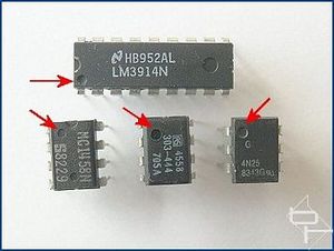
Correct orientation of the chips is vital. Failure to do so will not only stop the circuits from working but may well result in the chips being destroyed. The first picture below shows how to identify which is pin 1 on the chips. Pin 1 is identified by a round dimple next to it, indicated by the arrows. Note there are sometimes other indentations on the chip, be careful not to get mixed up.
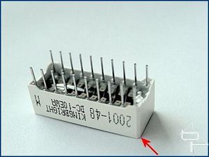
The second picture shows the LED array with the bevelled corner indicated by the arrow. This bevel indicates which of the two rows of pins are the anodes. If you use a different array be sure to check which row are the anodes in case it differs.
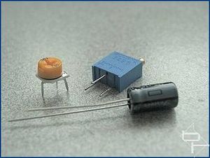
Moving on to the variable resistors, the PCB layout has been designed to accept either multiturn, (blue in picture), or cheap miniature single turn, (yellow), controls. I recommend using the multiturn type since it makes for much easier setting up of the circuit, especially with regard to fine tuning the display for a really "fluid" movement. The capacitors used are polarised, meaning they need to be connected the correct way round. The shorter of the two legs is the negative.
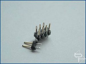
The two pin headers used for connecting to the board come in strips as shown below. Each header pair is snapped off the strip as required. I actually removed these headers from an old ISA modem card. (Check out old sound and VGA cards, recycling rules!). It is not necessary to use the headers, it just make connecting to the board convenient, especially switching between DOT and BAR modes. A switch could be used instead to switch modes if desired.
There are three controls to adjust. Starting with the easiest, VR1. This determines the speed of the animation and is adjusted purely to suit your taste.
VR2 sets the span or range of animation. In other words, at what point if and when the last LED lights. VR3 determines the start point or when the first LED lights. It sounds complicated, but all it means is that VR2 and VR3 are adjusted so the the animation moves smoothly between the first to last LEDs. E.G. setting VR2 too low will prevent the last LED(s) from lighting. Setting it too high will cause the last LED to stay lit for too long, making the animation "jerky". VR2 and VR3 interact to some extent, so adjusting one may require a small readjustment to the other.
If the "Gated" version is to be used, then replacing C3 with a temporary wire link will make setting up the circuit considerably easier. Once set up, the link is replaced with C3.
The following procedure should make it easy and give a good starting point for setting up the circuit, leaving only fine adjustments to be made. These "tweaks" can be made by adjusting VR2/VR3 whilst watching the display for the most pleasing animation. You will need a digital multimeter set to measure resistance. The values given below were arrived at by measuring each of the circuits after they had been fully set up. All of the measurements for all of the boards were within a few 10s of Ohms of each other indicating that this method of setting up would be repeatable.
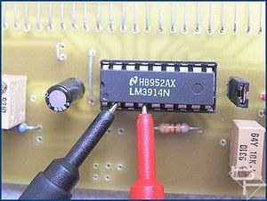
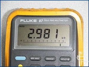
With NO POWER connected to the circuit, measure the resistance across pins 2 and 4 of IC2. Adjust VR3 until the reading is about 3KOhms, (3000 Ohms).
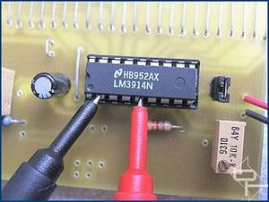
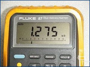
Measure the resistance across pins 2 and 5 of IC2. Adjust VR2 until the reading is about 1.275KOhms, (1275 Ohms).
The above settings should give a good basis to work from for final tweaking should it be necessary. With the circuit running in DOT mode, set VR1 for a comfortable speed and adjust VR3 and VR2 for smooth animation at the display extremes. VR3 affects LED1 and VR2 adjusts LED 10. Correctly adjusted, the LED should "move" back and forth with a smooth flowing action.
Before moving on, some thoughts for experimenters.
Instead of soldering the LEDs directly to the board, they can be connected using wires. This will allow the LEDs to be arranged in different patterns or shapes. The wires should be kept reasonably short to prevent instability of the LM3914 chip. I would recommend keeping the wires to less than 12"/300mm although longer lengths may well work fine.
Try using different coloured LEDs.
An LM3915 can be used instead of the LM3914. The LM3915 is a logarithmic version of the '3914 and produces a display in which the LEDs "move" faster as more LEDs are lit up. This is quite a visually interesting variation especially when using the 20 LED versions of the circuit.
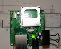
The next part of this article is the HDD activity meter
Any questions or comments about these circuits can be raised on the forum here.
Before we get to the setting up of the circuit, a few words about some of the components used.
You will notice that I have used sockets for the chips. This is purely for my convenience since I often "steal" parts from old projects when developing new ones. You can use sockets if you wish but they are by no means necessary.
Correct orientation of the chips is vital. Failure to do so will not only stop the circuits from working but may well result in the chips being destroyed. The first picture below shows how to identify which is pin 1 on the chips. Pin 1 is identified by a round dimple next to it, indicated by the arrows. Note there are sometimes other indentations on the chip, be careful not to get mixed up.
The second picture shows the LED array with the bevelled corner indicated by the arrow. This bevel indicates which of the two rows of pins are the anodes. If you use a different array be sure to check which row are the anodes in case it differs.
Moving on to the variable resistors, the PCB layout has been designed to accept either multiturn, (blue in picture), or cheap miniature single turn, (yellow), controls. I recommend using the multiturn type since it makes for much easier setting up of the circuit, especially with regard to fine tuning the display for a really "fluid" movement. The capacitors used are polarised, meaning they need to be connected the correct way round. The shorter of the two legs is the negative.
The two pin headers used for connecting to the board come in strips as shown below. Each header pair is snapped off the strip as required. I actually removed these headers from an old ISA modem card. (Check out old sound and VGA cards, recycling rules!). It is not necessary to use the headers, it just make connecting to the board convenient, especially switching between DOT and BAR modes. A switch could be used instead to switch modes if desired.
There are three controls to adjust. Starting with the easiest, VR1. This determines the speed of the animation and is adjusted purely to suit your taste.
VR2 sets the span or range of animation. In other words, at what point if and when the last LED lights. VR3 determines the start point or when the first LED lights. It sounds complicated, but all it means is that VR2 and VR3 are adjusted so the the animation moves smoothly between the first to last LEDs. E.G. setting VR2 too low will prevent the last LED(s) from lighting. Setting it too high will cause the last LED to stay lit for too long, making the animation "jerky". VR2 and VR3 interact to some extent, so adjusting one may require a small readjustment to the other.
If the "Gated" version is to be used, then replacing C3 with a temporary wire link will make setting up the circuit considerably easier. Once set up, the link is replaced with C3.
The following procedure should make it easy and give a good starting point for setting up the circuit, leaving only fine adjustments to be made. These "tweaks" can be made by adjusting VR2/VR3 whilst watching the display for the most pleasing animation. You will need a digital multimeter set to measure resistance. The values given below were arrived at by measuring each of the circuits after they had been fully set up. All of the measurements for all of the boards were within a few 10s of Ohms of each other indicating that this method of setting up would be repeatable.
With NO POWER connected to the circuit, measure the resistance across pins 2 and 4 of IC2. Adjust VR3 until the reading is about 3KOhms, (3000 Ohms).
Measure the resistance across pins 2 and 5 of IC2. Adjust VR2 until the reading is about 1.275KOhms, (1275 Ohms).
The above settings should give a good basis to work from for final tweaking should it be necessary. With the circuit running in DOT mode, set VR1 for a comfortable speed and adjust VR3 and VR2 for smooth animation at the display extremes. VR3 affects LED1 and VR2 adjusts LED 10. Correctly adjusted, the LED should "move" back and forth with a smooth flowing action.
Before moving on, some thoughts for experimenters.
Instead of soldering the LEDs directly to the board, they can be connected using wires. This will allow the LEDs to be arranged in different patterns or shapes. The wires should be kept reasonably short to prevent instability of the LM3914 chip. I would recommend keeping the wires to less than 12"/300mm although longer lengths may well work fine.
Try using different coloured LEDs.
An LM3915 can be used instead of the LM3914. The LM3915 is a logarithmic version of the '3914 and produces a display in which the LEDs "move" faster as more LEDs are lit up. This is quite a visually interesting variation especially when using the 20 LED versions of the circuit.
The next part of this article is the HDD activity meter
Any questions or comments about these circuits can be raised on the forum here.
RELATED ARTICLES


MSI MPG Velox 100R Chassis Review
October 14 2021 | 15:04

Want to comment? Please log in.