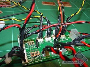
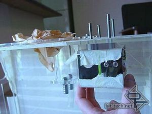
MPP wired up with inline resistors on all power connections. Wiring up the resistors here allows me to be able to plug any LED into any socket without worry and will save me having to try and find a way of fitting/hiding a bulging resistor inside my LED holders. I took another break and checked the fit again (check and test, check and test...)
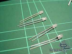
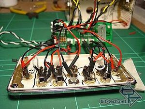
The 3mm LEDs for the divider were Sanded with 320 grit to diffuse them and the ends flattened to break up the curvature of the lens and give a more even brightness. The LED power was then wired up. I generally stuck with correct wire colours throughout the mod (i.e. 12v=yellow, 5v=red, GND=black) to make the wiring task a lot less confusing.
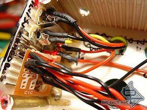
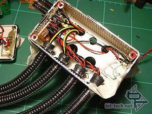
I wired up my 5v/GND from the PSU AUX line, via a switch, to this PCB. It acts as a junction with 5v/GND going in and several 5v/GNDs going out. In the right-hand image can be seen the two DVD drive power lines on the left and 4 PC Rider+ LED controller power lines running through the two right-hand stainless hoses.
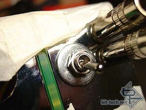
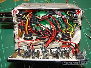
A switch was wired to the 4 PC Riders. If I get tired of all those flashing lights - I can turn em off. I'll need to remove the case side panel though as the switch isn't accessible from the outside, but I thought about this and decided it would stop cheeky people at LANs from messing with my lights. Once wired up the front part of the junction box was then ready to be closed. The MPP was a bit of a tight fit! Only a very carefully planned drawing saved me from total confusion:
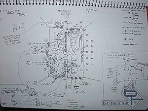
Hey... at least I can understand it!

MSI MPG Velox 100R Chassis Review
October 14 2021 | 15:04


Want to comment? Please log in.