Power, power, everywhere...
Someone in the modding forums once asked what people had done to their PSUs. Here's what I did with mine:
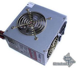
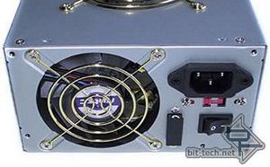
The stock Antec 550w all boring and grey - nice gold grills though... pity they are going to go. The one I got was a very tasty silver sleeved one from www.performance-pcs.com but I decided early on that I was going to rip all that tasty sleeving off in favour of something more original (sorry performance-PCs!). The rear fan has also been changed to an 80mm Aluminium/chrome instead of the stock Antec fan.
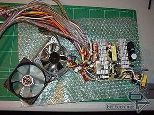
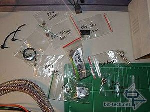
I took the PSU apart in order to get the covers chromed. Luckily I started modding it straight out of the box so with this, and the weeks it had been sitting around before I started on it, the capacitors had well and truly discharged. I Took care to label all the screws, etc. As it turned out when I went to put it back together a few weeks later I was glad I had done this as it made the whole reassembly much easier.
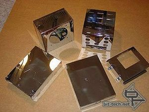
Once again, here are the PSU covers chromed. You can see them in the top left of the picture above (along with some other chrome work). They look amazing in reality - the camera has a hard time capturing the sheer quality of the finish.
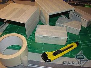
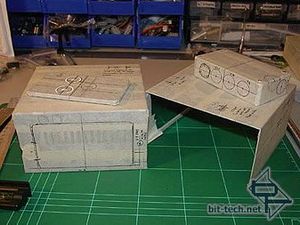
I started by covering everything in masking tape for ease of marking holes and also to protect the chrome finish from grubby fingers and scratches/slipping drill bits etc. Also to be used in the PSU mod are three (chromed) project boxes from RS components. I also marked everything for drilling. There was a lot of measuring. A set-square and a calculator became essential items. The very basic-level concept was to have the power cables from the PSU run into a junction box and then individual power lines running from there to each device in the system.
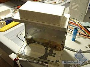
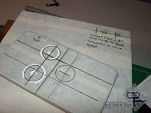
The PSU Cover showing the positioning of the PSU junction box and the junction box holes marked up. Also shown are the PSU top cover holes for the power to the PSU fans as I am taking the fans to a PWM fan controller on the front panel. The old variable voltage fan connections will still be used to power voltage indicators.
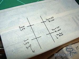
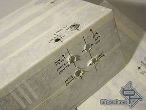
I marked the holes for LEDs and then drilled them, and also drilled holes for four 3.5mm mono jack sockets - used to run DC power to four of the LEDs. Why didn't I just run them from inside the PSU? Well firstly, as the cabling is to be a feature of this mod, this allowed me to run some more cables and jack plugs and, secondly, because it allows me the flexibility to later on re-patch the LEDs to other sources (like a PC Rider+ LED controller) if I want.
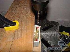
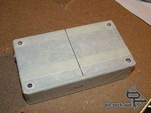
I drilled out the threaded, lid-attaching corner posts of the first project box. I drilled out all the metal in there and carried the holes right through to the other side. The box bolts onto the PSU and the bolts also extend out to hold the lid onto the front.
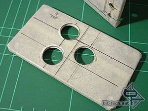
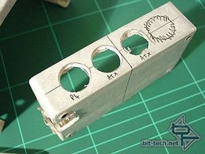
19mm (3/4") holes drilled in the box lid using a drill press and a Step Drill. The big hole in the left side here was drilled into the corner - this is where all the cables exiting the PSU will pass into the junction box.
Someone in the modding forums once asked what people had done to their PSUs. Here's what I did with mine:


The stock Antec 550w all boring and grey - nice gold grills though... pity they are going to go. The one I got was a very tasty silver sleeved one from www.performance-pcs.com but I decided early on that I was going to rip all that tasty sleeving off in favour of something more original (sorry performance-PCs!). The rear fan has also been changed to an 80mm Aluminium/chrome instead of the stock Antec fan.


I took the PSU apart in order to get the covers chromed. Luckily I started modding it straight out of the box so with this, and the weeks it had been sitting around before I started on it, the capacitors had well and truly discharged. I Took care to label all the screws, etc. As it turned out when I went to put it back together a few weeks later I was glad I had done this as it made the whole reassembly much easier.

Once again, here are the PSU covers chromed. You can see them in the top left of the picture above (along with some other chrome work). They look amazing in reality - the camera has a hard time capturing the sheer quality of the finish.


I started by covering everything in masking tape for ease of marking holes and also to protect the chrome finish from grubby fingers and scratches/slipping drill bits etc. Also to be used in the PSU mod are three (chromed) project boxes from RS components. I also marked everything for drilling. There was a lot of measuring. A set-square and a calculator became essential items. The very basic-level concept was to have the power cables from the PSU run into a junction box and then individual power lines running from there to each device in the system.


The PSU Cover showing the positioning of the PSU junction box and the junction box holes marked up. Also shown are the PSU top cover holes for the power to the PSU fans as I am taking the fans to a PWM fan controller on the front panel. The old variable voltage fan connections will still be used to power voltage indicators.


I marked the holes for LEDs and then drilled them, and also drilled holes for four 3.5mm mono jack sockets - used to run DC power to four of the LEDs. Why didn't I just run them from inside the PSU? Well firstly, as the cabling is to be a feature of this mod, this allowed me to run some more cables and jack plugs and, secondly, because it allows me the flexibility to later on re-patch the LEDs to other sources (like a PC Rider+ LED controller) if I want.


I drilled out the threaded, lid-attaching corner posts of the first project box. I drilled out all the metal in there and carried the holes right through to the other side. The box bolts onto the PSU and the bolts also extend out to hold the lid onto the front.


19mm (3/4") holes drilled in the box lid using a drill press and a Step Drill. The big hole in the left side here was drilled into the corner - this is where all the cables exiting the PSU will pass into the junction box.

MSI MPG Velox 100R Chassis Review
October 14 2021 | 15:04


Want to comment? Please log in.