The Front-Panel Switches ...
The front bezel of the case will be modded to bring it in to line with the themes of the case. Better make a start then:
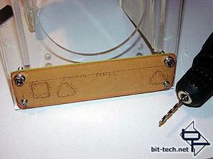
The new front bezel for my case switches. Note the corners - I changed my mind about these and rounded them off even more (you can see I have marked them up already). The square and two triangles mark the existing holes in the case bezel where the original case switches went. I ignored these holes entirely and just drilled like they weren\'t there - although where I actually drilled my holes in the first place was affected by these original holes. e.g. the LED holders needed to be located away from these original holes so they would have something to actually attach to!
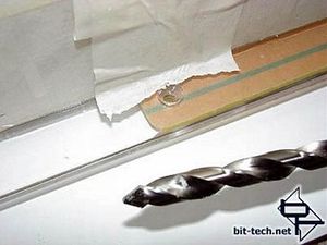
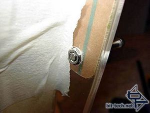
For various reasons the smaller bolts I used on the front panel cover were only there to hold the cover on, and not the bezel to the case. Not having a tap and die to tap the holes I had drilled I simply chamfered the rear of the holes with a much larger plexi drill so the small nut I used would sit flush and not interfere when attaching the removable front to the case. Checking ... needed a little more drilling before it sat flush.
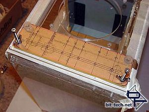
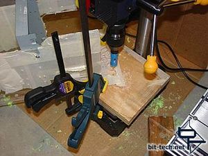
Yep, sits on there nicely now. The clear thumbscrews were the ones that came with the case. Hole positions are marked - It took a few tries before I settled on the final positions due to the pre-existing holes in the bezel and other factors like the position of the radiator adjacent to the LEDs etc. Right after the right-hand shot was taken, I then went on to drill 12 pilot holes through all 3 layers of the front switch panel. This was to ensure all the differing sized holes in each layer lined up properly. I also drilled 19mm holes for the Vandal switches (they will be attached to the removable front bezel shown here). 11mm holes (plexi-drill) were also drilled for the heads of the LED holders to fit into - the LED holders will be attached to the actual case itself and remain in place whenever the front bezel is removed.
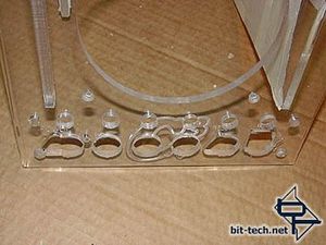
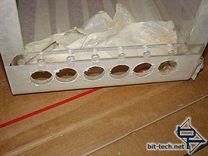
You can see the holes for the stainless steel vandal-resistant switches and LED holder holes in the removable front bezel. The case itself was drilled starting with 8mm holes (plexi drill) for the LED holders as they will attach to this part of the case. For the larger holes which were designed to be clear of the rear of the vandal switches I used a holesaw. I had great difficulty getting them straight. Despite drilling pilot holes to start with, they were a few mm out from each other - quite noticeable in reality though in the picture not so much - who says the camera never lies ...? Also the nuts backing the Vandal switches on the removable bezel wouldn\'t fit properly as a result. My solution...
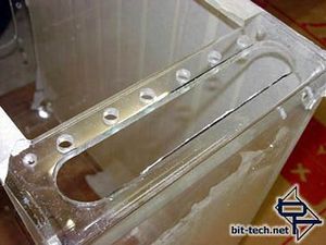
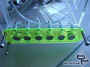
...using a holesaw on my cordless drill I enlarged the holes at each end then used a hacksaw and dremel to do the \'straight\' sides - later filed/sanded/polished until they actually were straight. I ended up with lots of clearance for the vandal switch nuts and nice straight lines. Fortunately the holes for the LEDs lined up exactly in all 3 layers so I had no problems there. The neon green acrylic switch cover had 5mm LED holes drilled - 5mm so the end of the 5mm LEDs can insert partial-way into the cover. The large holes are 22mm and are the same size as the bezel on the switches so they fit snugly. The six switches are for Power, Reset and the four PC Rider+ LED controllers that will be used in the case. The bolts are just there to keep everything lined up and will be cut to length later.
You can just make out the \'C³\' on the front. I toyed with the idea of covering this up (and even prototyped a stainless steel cover, then a white acrylic cover) but the transparency of this part of the case looked the best. It is barely noticeable but provides a link to the cases origins, which I like.
When the LEDs light up the whole cover will light up just like the panel on the top of the PSU. (glowing panels being a fairly strong theme in this system).
The front bezel of the case will be modded to bring it in to line with the themes of the case. Better make a start then:

The new front bezel for my case switches. Note the corners - I changed my mind about these and rounded them off even more (you can see I have marked them up already). The square and two triangles mark the existing holes in the case bezel where the original case switches went. I ignored these holes entirely and just drilled like they weren\'t there - although where I actually drilled my holes in the first place was affected by these original holes. e.g. the LED holders needed to be located away from these original holes so they would have something to actually attach to!


For various reasons the smaller bolts I used on the front panel cover were only there to hold the cover on, and not the bezel to the case. Not having a tap and die to tap the holes I had drilled I simply chamfered the rear of the holes with a much larger plexi drill so the small nut I used would sit flush and not interfere when attaching the removable front to the case. Checking ... needed a little more drilling before it sat flush.


Yep, sits on there nicely now. The clear thumbscrews were the ones that came with the case. Hole positions are marked - It took a few tries before I settled on the final positions due to the pre-existing holes in the bezel and other factors like the position of the radiator adjacent to the LEDs etc. Right after the right-hand shot was taken, I then went on to drill 12 pilot holes through all 3 layers of the front switch panel. This was to ensure all the differing sized holes in each layer lined up properly. I also drilled 19mm holes for the Vandal switches (they will be attached to the removable front bezel shown here). 11mm holes (plexi-drill) were also drilled for the heads of the LED holders to fit into - the LED holders will be attached to the actual case itself and remain in place whenever the front bezel is removed.


You can see the holes for the stainless steel vandal-resistant switches and LED holder holes in the removable front bezel. The case itself was drilled starting with 8mm holes (plexi drill) for the LED holders as they will attach to this part of the case. For the larger holes which were designed to be clear of the rear of the vandal switches I used a holesaw. I had great difficulty getting them straight. Despite drilling pilot holes to start with, they were a few mm out from each other - quite noticeable in reality though in the picture not so much - who says the camera never lies ...? Also the nuts backing the Vandal switches on the removable bezel wouldn\'t fit properly as a result. My solution...


...using a holesaw on my cordless drill I enlarged the holes at each end then used a hacksaw and dremel to do the \'straight\' sides - later filed/sanded/polished until they actually were straight. I ended up with lots of clearance for the vandal switch nuts and nice straight lines. Fortunately the holes for the LEDs lined up exactly in all 3 layers so I had no problems there. The neon green acrylic switch cover had 5mm LED holes drilled - 5mm so the end of the 5mm LEDs can insert partial-way into the cover. The large holes are 22mm and are the same size as the bezel on the switches so they fit snugly. The six switches are for Power, Reset and the four PC Rider+ LED controllers that will be used in the case. The bolts are just there to keep everything lined up and will be cut to length later.
You can just make out the \'C³\' on the front. I toyed with the idea of covering this up (and even prototyped a stainless steel cover, then a white acrylic cover) but the transparency of this part of the case looked the best. It is barely noticeable but provides a link to the cases origins, which I like.
When the LEDs light up the whole cover will light up just like the panel on the top of the PSU. (glowing panels being a fairly strong theme in this system).

MSI MPG Velox 100R Chassis Review
October 14 2021 | 15:04


Want to comment? Please log in.