
Wiring the Display
I had a problem with the module in that if an actual serial plug was to be inserted into the back of the VFD, it would have protruded out the back of the box and required a huge hole, etc. Also it would have looked like a serial cable! To save on space and aesthetics I came up with a plan:
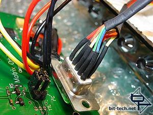
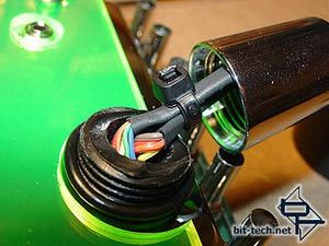
Using some multicoloured ribbon cable and a cut apart 9 pin serial plug I came up with this: The wires are soldered to individual pins from my old serial plug, covered in heat shrink and then inserted into the VFD. The value of multicolored cable and numbered holes on the VFD really showed! I knew that only a few of the pins are actually used but wasn\'t quite sure which ones. To avoid making a mistake and to add a bit of strength to the cable/plug join, I wired them all!
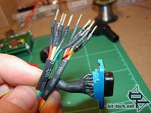
Here\'s my home-made serial cable - pins on one end and a plug on the other.
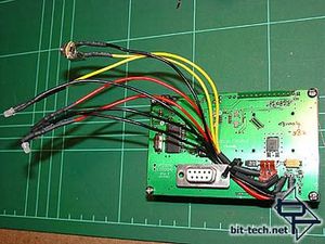
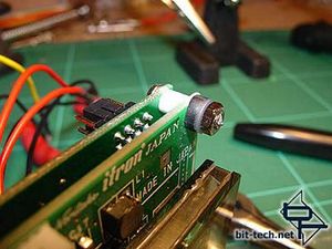
I wired up 12v power (to a 3.5 jack socket) - 12v as I got a \'Wide Voltage\' model VFD. I also wired a 3mm white LED to the 12v in and a pair of 3mm white LEDs to the 5v GPO (all with appropriate resistors). There is an in-line resistor on the GPO but I bypassed it by soldering a bridge on the PCB as I wanted to use the resistors I already had for the hi-brightness LEDs I was putting in. I also snipped off the protruding bolts, that had previously held the VFD to its old bay insert, with a pair of pliers.
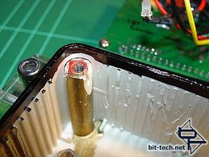
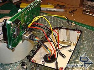
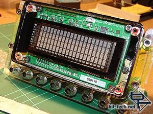
A black permanent marker was used to cover all the beige plastic around the inner edge of the box. This was all part of the plan to make the plexi front a black mirror. At this stage I started to wire the display into the housing.
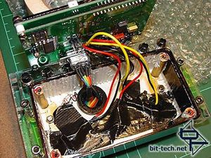
All wired up! I used hot-glue to secure the LEDs and then covered them in black duct tape to prevent any spillage of light from the rear LEDs back into the housing to mess up my mirror effect. While I was hot gluing I also glued the serial cable pins in place extra securely. A cable tie applied around the serial cable serves to prevent the cable being pulled out once the chrome fitting is screwed on.
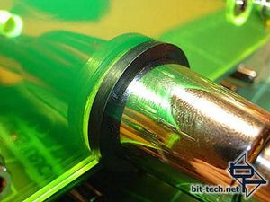
To get this effect I first attached two rubber o-rings (seen in the right-hand picture above) and then slid a stepped rubber ring over the top. The o-rings acted to secure the step-ring where it inserts into the neon plexi hole. It\'s kind of difficult to explain. Basically the rubber surround won\'t come loose! The VFD was a perfect fit and it doesn\'t move a mm - in fact, I had had to get a craft knife and shave off every one of the little ribs around the edge of the box as well as trim the corner posts to fit it in! I took a permanent marker and blacked out all around the edge of the VFD display (including the sides of the glass) to minimize light spilling and to fit in with my \'black mirror\' effect.
I had a problem with the module in that if an actual serial plug was to be inserted into the back of the VFD, it would have protruded out the back of the box and required a huge hole, etc. Also it would have looked like a serial cable! To save on space and aesthetics I came up with a plan:
Using some multicoloured ribbon cable and a cut apart 9 pin serial plug I came up with this: The wires are soldered to individual pins from my old serial plug, covered in heat shrink and then inserted into the VFD. The value of multicolored cable and numbered holes on the VFD really showed! I knew that only a few of the pins are actually used but wasn\'t quite sure which ones. To avoid making a mistake and to add a bit of strength to the cable/plug join, I wired them all!
Here\'s my home-made serial cable - pins on one end and a plug on the other.
I wired up 12v power (to a 3.5 jack socket) - 12v as I got a \'Wide Voltage\' model VFD. I also wired a 3mm white LED to the 12v in and a pair of 3mm white LEDs to the 5v GPO (all with appropriate resistors). There is an in-line resistor on the GPO but I bypassed it by soldering a bridge on the PCB as I wanted to use the resistors I already had for the hi-brightness LEDs I was putting in. I also snipped off the protruding bolts, that had previously held the VFD to its old bay insert, with a pair of pliers.
A black permanent marker was used to cover all the beige plastic around the inner edge of the box. This was all part of the plan to make the plexi front a black mirror. At this stage I started to wire the display into the housing.
All wired up! I used hot-glue to secure the LEDs and then covered them in black duct tape to prevent any spillage of light from the rear LEDs back into the housing to mess up my mirror effect. While I was hot gluing I also glued the serial cable pins in place extra securely. A cable tie applied around the serial cable serves to prevent the cable being pulled out once the chrome fitting is screwed on.
To get this effect I first attached two rubber o-rings (seen in the right-hand picture above) and then slid a stepped rubber ring over the top. The o-rings acted to secure the step-ring where it inserts into the neon plexi hole. It\'s kind of difficult to explain. Basically the rubber surround won\'t come loose! The VFD was a perfect fit and it doesn\'t move a mm - in fact, I had had to get a craft knife and shave off every one of the little ribs around the edge of the box as well as trim the corner posts to fit it in! I took a permanent marker and blacked out all around the edge of the VFD display (including the sides of the glass) to minimize light spilling and to fit in with my \'black mirror\' effect.


MSI MPG Velox 100R Chassis Review
October 14 2021 | 15:04

Want to comment? Please log in.