A Black Mirror ...
To aid in getting the effect I wanted with the tinted acrylic covering the VFD, I ...
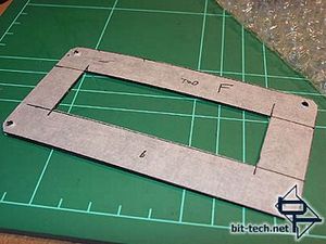
... carefully measured and cut out a cover made from ...

... the black plastic cover of my sketchbook! Who says gnomes don\'t recycle?
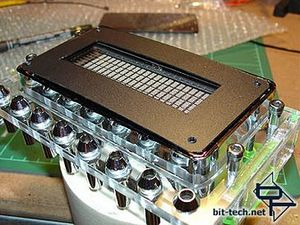
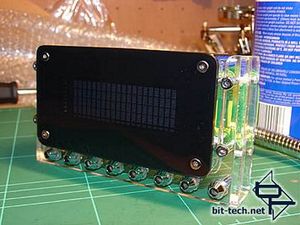
The plastic cover fits in place over the VFD and, combined with the black edges you saw earlier, serves to black out the entire front of the unit apart from the dot matrix characters themselves. The right-hand image was taken with a bright, direct flash - you can barely make out that there is a display under there.
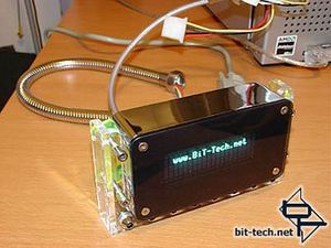
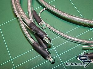
Running some tests with LCDC using a serial cable and power from my other computer - works fine! After I played with LCDC I wired up some LEDs - here waiting to go under the heat gun. The 5mm heat shrink was my way of securing them in the chrome holders as, when shrunk onto the cables, they have to be forced into the holders. Thanks to the wonder of friction, only an almighty yank would get them out of there. This keeps the connection clean and means I don\'t have to use glue (able to change LEDs easily then).

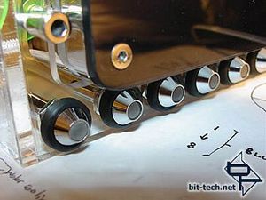
A nice clean fit with black rubber surrounds completing the LED mounts. The LEDs were sanded and then the ends filed flat to sit flush with the chrome holder. Why? Because I can. Note the countersunk socket head screws holding the tinted plexi cover in place - polished stainless steel is my friend.
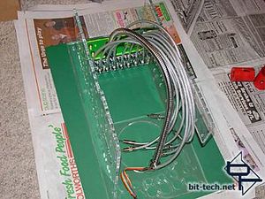
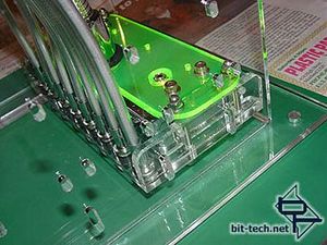
To mount the VFD module flush with the face of the front bezel I laid it flat, worked out where the holes needed to go, marked them and ...
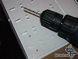
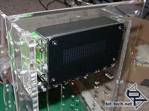
... drilled them with a plexi-point drill then mounted the finished module into the drive cage.
To aid in getting the effect I wanted with the tinted acrylic covering the VFD, I ...

... carefully measured and cut out a cover made from ...

... the black plastic cover of my sketchbook! Who says gnomes don\'t recycle?


The plastic cover fits in place over the VFD and, combined with the black edges you saw earlier, serves to black out the entire front of the unit apart from the dot matrix characters themselves. The right-hand image was taken with a bright, direct flash - you can barely make out that there is a display under there.


Running some tests with LCDC using a serial cable and power from my other computer - works fine! After I played with LCDC I wired up some LEDs - here waiting to go under the heat gun. The 5mm heat shrink was my way of securing them in the chrome holders as, when shrunk onto the cables, they have to be forced into the holders. Thanks to the wonder of friction, only an almighty yank would get them out of there. This keeps the connection clean and means I don\'t have to use glue (able to change LEDs easily then).


A nice clean fit with black rubber surrounds completing the LED mounts. The LEDs were sanded and then the ends filed flat to sit flush with the chrome holder. Why? Because I can. Note the countersunk socket head screws holding the tinted plexi cover in place - polished stainless steel is my friend.


To mount the VFD module flush with the face of the front bezel I laid it flat, worked out where the holes needed to go, marked them and ...


... drilled them with a plexi-point drill then mounted the finished module into the drive cage.

MSI MPG Velox 100R Chassis Review
October 14 2021 | 15:04


Want to comment? Please log in.