
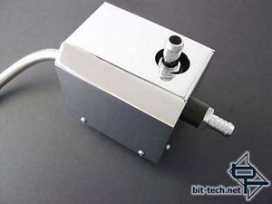
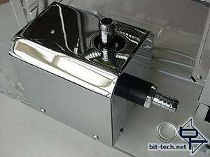
Final Pump Assembly...
Time to start putting the pump together:
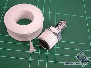
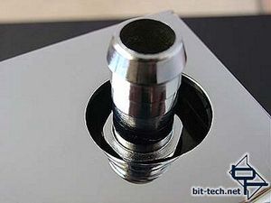
Like a good gnome I wrapped the threads of the pump fittings with Teflon tape, to make a tight seal...
...and screwed the fittings in place.
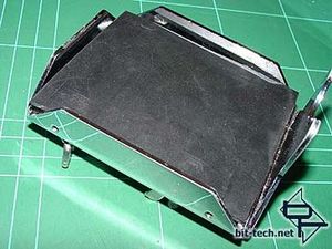
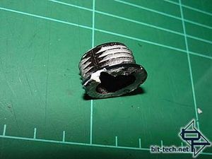
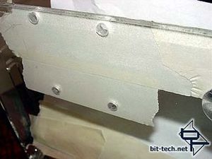
The rubber pieces were also tidied up, test fitted and trimmed some more.
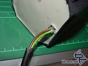
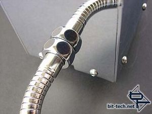
Because the power cord emerges from one side of the rear, and I wanted to bring it across to the centre, I had to strip the insulation off a section of the wiring to enable it to both bend easier and actually fit in the couple of mm that existed between the pump and the rear cover! I also filed a notch in the fitting to accommodate the wires.
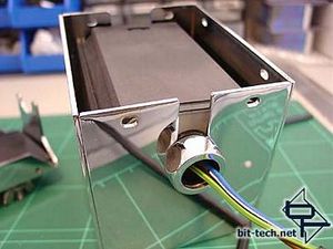
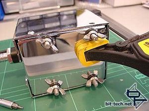
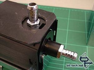
Perfect. Time to add the base - here using the pressure of a clamp to compress the rubber inside and allow the holes to line up. It took a lot of pressure to line them up correctly. The wing nuts are there to hold the bolts in place while I put the cover together. They were removed afterwards as the pressure of the pump sitting on the rubber inside the cover prevents them from pushing back to the inside.
All done. I still plan to do some modding on the power cable as it will be going to a PCI relay card with a separate earth wire going, via a jack plug, to the PSU.
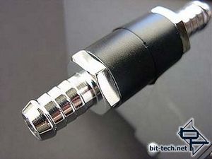
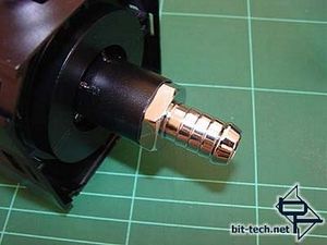
The (formerly brass) barbs look good chromed and the black vinyl dye looks much better IMHO than the Grey plastic.
The new screws are a big improvement as well.
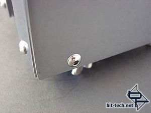
Mounting...
6mm holes were drilled in the case floor to mount it. The rubber grommets used around the mounting bolts provide a nice soft cushion that should soak up any vibration from the pump motor. The pump sits happily in its final resting place.
So there you have it - a 1250 in a 1048 cover. It felt like squashing a big souped-up engine into a compact car! The FMJ gives a much better look than the bare pump and will prevent EMI as well. Form as well as function.
Time to start putting the pump together:
Like a good gnome I wrapped the threads of the pump fittings with Teflon tape, to make a tight seal...
...and screwed the fittings in place.
The rubber pieces were also tidied up, test fitted and trimmed some more.
Because the power cord emerges from one side of the rear, and I wanted to bring it across to the centre, I had to strip the insulation off a section of the wiring to enable it to both bend easier and actually fit in the couple of mm that existed between the pump and the rear cover! I also filed a notch in the fitting to accommodate the wires.
Perfect. Time to add the base - here using the pressure of a clamp to compress the rubber inside and allow the holes to line up. It took a lot of pressure to line them up correctly. The wing nuts are there to hold the bolts in place while I put the cover together. They were removed afterwards as the pressure of the pump sitting on the rubber inside the cover prevents them from pushing back to the inside.
All done. I still plan to do some modding on the power cable as it will be going to a PCI relay card with a separate earth wire going, via a jack plug, to the PSU.
The (formerly brass) barbs look good chromed and the black vinyl dye looks much better IMHO than the Grey plastic.
The new screws are a big improvement as well.
Mounting...
6mm holes were drilled in the case floor to mount it. The rubber grommets used around the mounting bolts provide a nice soft cushion that should soak up any vibration from the pump motor. The pump sits happily in its final resting place.
So there you have it - a 1250 in a 1048 cover. It felt like squashing a big souped-up engine into a compact car! The FMJ gives a much better look than the bare pump and will prevent EMI as well. Form as well as function.


MSI MPG Velox 100R Chassis Review
October 14 2021 | 15:04

Want to comment? Please log in.