
The Power Supplies - Assembly And Wiring
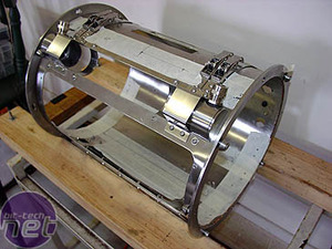
The row of holes in the box were designed to line up with the row above them (in the PSU bracket). To mount the bracket, the case was leveled, along with the bracket, and marks made for drilling. This was a lot more difficult than it sounds: the bracket sits on the inside, but I couldn't drill from the inside and thus couldn't use the bracket as a template for marking!
In the end had to do it all through some hardcore measuring. This involved more than a few calculations to translate the width of the bracket into an arc, based on the diameter of the case, to allow me to measure around the curve and mark the holes at the correct distances. Not for the first time in the project, I wished I'd paid more attention in maths class in school!
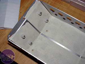
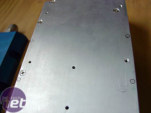
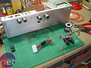
A double row of holes were drilled, the rearmost being shown here. I also drilled the box for the PCBs (first lot shown here with the nylon stand-offs I used).
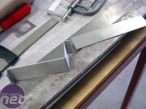
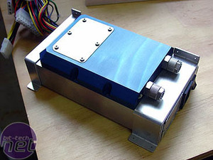
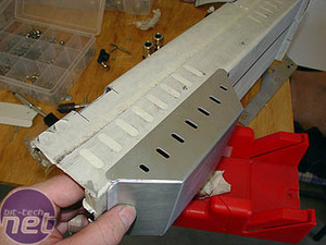
To fix the PSUs to the bracket, I made some aluminium pieces to fit over the PSUs. These were designed to fit exactly around the waterblock on top. Not only do they hold the PSUs down, but they prevent them from sliding once the waterblock is attached.
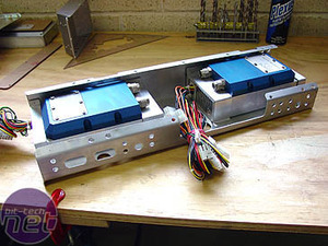
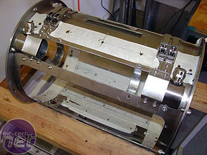
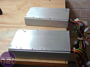
The arrangement of both power supplies in the bracket shows how the waterblock fittings face each other to allow for less run of tubing when daisy-chaining them together. To mount the waterblocks onto the PSUs I marked them, using the blocks as a template.
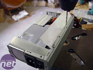
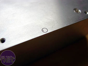
The PSU covers were marked, removed, drilled and tapped to M4. There was a folded-over section along one edge of the PSU casing which needed to be drilled separately. I used masking tape and a lot of care to prevent any metal shavings going inside the workings of the PSU and causing a short later.
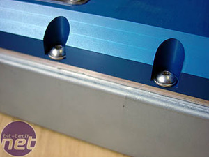
The covers were reassembled and the waterblocks screwed down with short M4 screws and washers.

The tape came off and I polished them, before doing some more wiring. I had originally wanted all the wiring to be red to match the theme colours of black, red and stainless steel. I saw the result of someone doing this later, in Bill Ryder's Project KOS-MOS, and was very impressed. I also wanted to use steel wiring glands to run wires everywhere, not only from the PSUs but also from the front displays, etc.
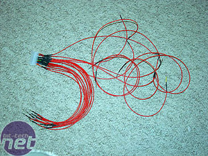
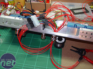
I tackled the ATX and 12v cables first, cutting, wiring and threading them through the glands.
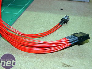
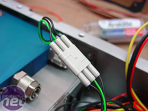
The cables looked great when done, thanks to carefully measuring the heat-shrink pieces to the same length and finishing with a set of black ATX and 12v plugs from Kustom PCs. Kustom PCs sent me an entire set of black plugs, including molex and fan plugs, and everything was re-wired using these. In my last project I had to paint my plugs black, but the ready-made plugs saved me a lot of hassle, not-to-mention looking more professional. The PC Link cable was plugged and tested also; it worked great.
RELATED ARTICLES


MSI MPG Velox 100R Chassis Review
October 14 2021 | 15:04

Want to comment? Please log in.