
Top Displays - Cutting And Covers
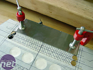
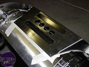
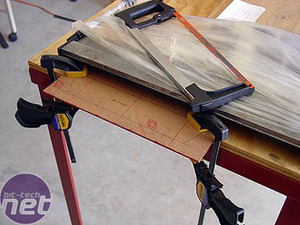
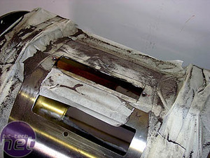
The stainless steel is so tough it is difficult to cut inside a line and then file it straight later, as you can do with aluminium. I came up with the idea of using another piece of steel as a guide, clamping it along the edge of the line to be cut. It worked brilliantly in keeping the dremel on the line, and I got beautifully straight cuts! Almost no filing was required.
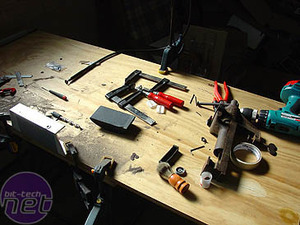
By the end of all this cutting, I'd made a bit of a mess, but the cover looked good.
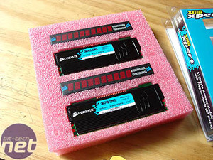
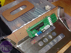
Just as I had finished the cover, a courier banged on the door and got a scare when I popped out of the garage with my goggles, mask, gloves and overalls on. It was my Corsair! The memory comes packaged as shown, and the displays were everything I'd imagined. Most importantly, I'd cut the holes the correct size!
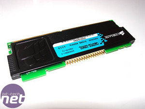
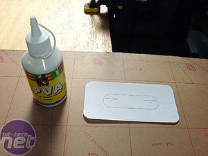
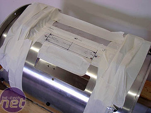
The 34-pin arrangement fitted the 34-pin plugs I'd bought from the local electronics shop. I had to shave a little off the corners of the PCB, next to the pins on the memory module, but the display modules required no work at all. To cut out the cover for the memory displays, I first drew the outline in Illustrator. I then stuck it to the protective paper on some red plexi.
I also drew up the outline of the cover that would sit in front of the VFD. Both this and the top cover were then cut out with a hacksaw. After all the acrylic work in my last project, I can now cut a ruler-straight line in plastic with a hacksaw. Who'd have thought?
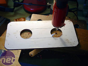
I used a holesaw, in my drill press, to cut the rounded ends of the centre opening (for the VFD switches). A hacksaw with the blade removed and re-attached, after passing it through one of the holes, served to cut the rest of the centre out. Some filing and sanding cleaned up the edges. I used progressively finer grades of sandpaper as I did the edges, to give a smooth finish.
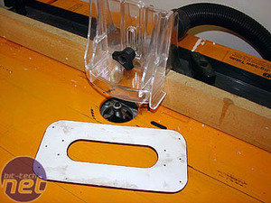
The final step in the top cover was to bevel the edges on my router table, with a 45-degree bearing bit. I also beveled the edges of the plexi at the front. The front cover was taped in place and marked for drilling.
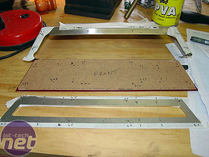
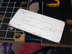
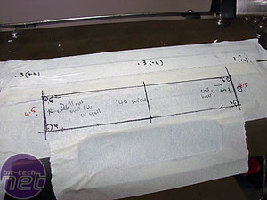
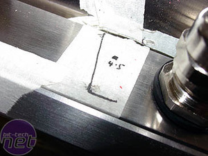
This part of the mod was pretty crazy. As the VFD was to be fastened to the inside of the plexiglas and the plexi and front bezel had to both screw together and screw to the top cover, they all had to be drilled differently. A hole might start as an M4 clearance hole in the bezel (so 5mm) then go to an M4 threaded hole in the plexi (so had to be drilled 3mm and tapped to M4), or as an M3 clearance in both bezel and plexi, or an M3 clearance (4mm) in bezel and a 2.5mm in the plexi (tapped to M3), and so on and so on (confused yet?). You can see I wrote the size of each hole in each piece right next to the mark for it. It was the only way to get it right.
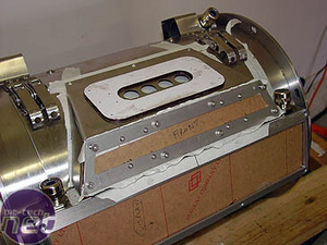
Once I'd drilled and/or tapped the 42-odd holes, the front went on perfectly.
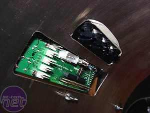
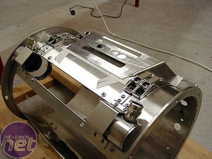
The VFD was attached with the four M3 screws that passed completely through the front cover and screwed right into the threaded stand-offs on the PCB. As the actual display part of the VFD is offset in the PCB, I centered the display part in the window. This means that the first and third pairs of M3 screws, from the left as you look at the front of the display, are dummies and don't hold the VFD in - they are simply there to balance the four screws that do! Confused still? Once assembled, the VFD and the switches fit neatly through the cutouts in the case.
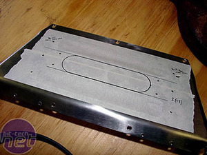
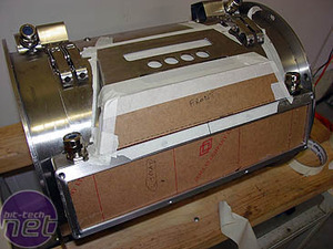
The late arrival of the Corsair displays meant I had to go back and cut an additional hole in the case to accommodate the bottom of the rearmost display. Using the top piece of plexi as a template, I also marked the top cover for drilling.
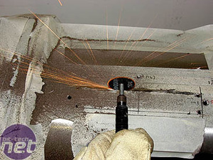
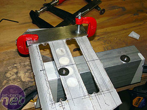
The top of the display box was marked for drilling, where the top cover will be screwed to it. I drilled the corners of the memory display hole and attacked it with the Dremel. More cut-off wheels sacrificed themselves like lemmings for the good of the project. Messy! (right) The detritus of a dozen Dremel wheels.
RELATED ARTICLES


MSI MPG Velox 100R Chassis Review
October 14 2021 | 15:04

Want to comment? Please log in.