Top Displays - Assembly And Hoses


It seemed that every time I blinked, there were more holes in the case! Some small touches were added to the front bezel: counter-sinking the small M3 holes for the VFD screws (and dummy screws).


I gave it a good polish, to the standard 280 grit used throughout the case. Careful attention was always paid to the direction of polishing, to ensure it looked right and matched the piece it was attached to. In this case the top cover had to be polished front-to-back, to match the polish on the main cylinder (which runs around the circumference). The bezel I polished lengthwise.


Four of the screws holding the top plexi piece on are much longer than necessary; they serve to hold the memory displays in place. You might have noticed the two extra holes in the top cover, and wondered what they were for....


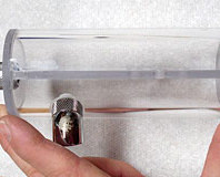
The holes are for a pair of Innovatek compression fittings. I tried the ones pictured initially, but later settled on the straight ones shown in the final images, with stainless steel springs added.


A closer look at the fittings. Finally, a small amount of work was needed, before I could screw the bezel down properly - here trimming a fraction off the tab to allow a corner screw to come through properly.


Here are a couple of images of the polished and nearly complete top cover. The protective paper stays on the plexi until the very last minute.


To really finish off the appearance of the case, I used some of the Innovatek brand tubing that came with my water-cooling gear. It was a bright red colour and a little lighter than the red of the plexi I used to cover the displays. To make it match, I cut off lengths of thick, black power cable and ran those inside the tubes. This darkened them enough to match the plexi. I also used some Innovatek anti-kink springs, forcing them into the fittings before tightening them. The two fittings I used on the top cover had springs already, as part of the fitting; these were zinc, however, so had to be replaced with the stainless steel, since the zinc was a different colour.


The two voltage indicators I bought to monitor the fan voltages aren't really necessary as the VFD can do this also. Still, many of the things one does in a mod are 'unnecessary' (but cool), so I wired these up and will mount them, one either side of the VFD display, with the seven-segment numbers being detached and run remotely from the PCB. Power goes in one end, and the voltage to be read goes in the other.

When I wired the radiator fans, I split the cable so the voltage going into the fans is also going into the indicator, via a 2-pin plug.

MSI MPG Velox 100R Chassis Review
October 14 2021 | 15:04


Want to comment? Please log in.