Cable Bay And Cover


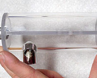
The cable bay cover is a hinged flap that opens to reveal the power, USB, firewire, audio, DVI and other ports and switches. The cover was cut from the same curved sheet as the back cover; I used the same thumb-bleeding methods to curve it to match the curve of the case.


The hinge is a stainless steel piano-type hinge. It came in a 6' length and it was a simple matter to cut a section off with the hacksaw. I'm sure I'll find a use for the remaining 5'6".


I filed the sharp corners of the hinge into a radius and covered it in masking tape, to mark where to drill the screw holes to attach the cover.


Holes were marked and drilled in the case and hinge. Once attached, you can see how I designed the slot cut into the top of the opening to be the same width as the barrel of the hinge, to ensure a nice fit.


Because the hinge attaches to the inside of the case and the cover will sit against the outside, there is a gap of 2mm (the thickness of the case steel) between hinge flap and cover. I needed to add a spacer, to enable the cover to close flat. I cut the spacer from a piece of red plexi. It worked perfectly. The plexi was 3mm thick to allow not only for the 2mm case thickness, but also for the 1mm thickness of the steel bezel over the IEC socket to the left of the opening.


10 x M4 screws hold the cover in place - more than truly necessary, but it adds to the heavy-duty industrial look of the project and is a tactic I've used throughout. The cable bay itself was designed to be recessed into the case and was cut out of 1.2mm aluminium. I then folded it, starting with the long sides....


...and then bending the ends over.


These images give a good idea of the design. The holes in the rear are for extension cables to attach to. From the left to right (above left) they are: network, 4 x audio, firewire, 2 x USB, VGA, DVI and DC power for the front display. The cable glands in each end run mains power, and switches for the PSUs & case lighting (red LEDs and CCFLs from Kustom PCs).
The extension cables are mostly FrontX extension cables from Kustom PCs. These were all removed from their plastic faces or bay covers and measured carefully to get the holes right in the cable bay. The socket end of each cable fits in the hole, and is fixed using the same method as with the original plastic faces. The plug ends then loop through special holes in the HDD rack, pass under the HDDs and plug into the motherboard. This method was adopted due to the dimensions of the case, forcing me to mount the motherboard with the ports to the side. The extra length of the extension cables allow the motherboard tray to slide out of the case (more on that in WMD Part III).


The cable gland at this end is for mains power to the PSUs. The two odd-shaped pieces in the centre of the second image are inserts for the cable bay; these sit between the edge of the rear opening and the ends of the bay (where the glands emerge). They mount the various switches for mains power, lighting and display power.


The bay cover effectively hides the plugs. In the second image, just next to HDDs, there is a strip of metal with slots. I made this piece to screw to the top of the cable bay - it hides the gap between the back of the bay and the HDD rack, concealing the cables. I had already made sure that all the extension cables (except the audio) were black, including the VGA, DVI and network extension cables. Once again it's attention to details like this, when combined with all the others, that seem to lift a project.

MSI MPG Velox 100R Chassis Review
October 14 2021 | 15:04


Want to comment? Please log in.