Timer - Mounting It


In WMD Part I I covered the construction of the timer box (seen here as 1:1 scale plans). In order to run the timer with the PCB inside the main case, and the LED board in the timer box, I needed to drill a hole to pass the wires through (15 of them). Here you can see where I have marked the hole for drilling to 20mm - the correct size to use a metal cable gland. The gland protrudes back into the main part of the case.


Also needed were some holes for cable glands in the top (for running the red hoses) and a smaller hole (to be covered by the top cover with VFD, etc) for running wires from the VFD to four indicator LEDs in the timer window. I also made and folded a pair of aluminium brackets to secure the LED board into the timer box.


I marked and cut the timer window out of 3mm red plexi (hacksaw again). I used the same shade of red as the plexi used in the original ElectronicsUSA housing. Normally, one would think placing such a dark sheet of plexi in front of any light source would dim it down horrendously. However, as the LEDs and displays use red lighting, this passes effortlessly through the red plexi with no effect on brightness.
A red filter transmits red light. The further the colour of the light is from red, the more it is blocked e.g. a blue light source would be almost completely blocked (you can see this in action in black-and-white photography, where a dark red filter on the lens turns a deep-blue sky so dark as to be almost black, but will turn reds almost white). Using the same coloured plexi in all the display covers also ensures that any variation in the shade of red of each display gets ironed out to the same shade. Anyway, that's my simple understanding of it, I'll leave the science of it to others.


On the back of the LED board are the standoffs used to mount it to the original, plastic case. The ones closest to the ends of the board are what I used as a reference when designing the mounting brackets. As the holes were already drilled in the LED board, it was better to use these and avoid trying to drill new ones. The holes at the ends of the brackets were drilled oblong, to allow for a bit of adjustment; they also meant I had some room to manoeuvre if my measurements were flawed, or I'd folded the ends over a millimetre or two out.


I re-used the nylon stand-offs from the original mounting. Once I'd worked out that everything was nice and straight and fitted, I marked and drilled both the brackets and the ends of the display box.


Four M4 stainless steel screws fixed the brackets to the display box. Like every screw used in the entire case, these were socket head screws (using an allen key rather than a screwdriver to tighten).


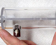
The Innovatek Fan-O-Matic Pro VFD is able to run separate indicator LEDs, and I wanted to use four of these in the case. I decided to mount them into the front window of the timer box. I modded the LED holders out of some stainless steel, M7 counter-sunk socket screws. I cut them down, so only the heads and a few mm of thread were left then clamped the heads in a vice to the drill press...


...and drilled 3.2mm holes right through the centre, using the socket on the end to guide the drill bit.


Once a washer and nut were added, I had custom-built LED holders, for 3mm LEDs. To mount these in the window, I marked it, checked the spacing of the holders, and drilled and countersunk the holes. Anytime I drilled plexi in the project, I used special 'Plexi-Point' drill bits - designed to avoid cracking or chipping the plexi. The LED holders were inserted and a 'nyloc' nut and washer added to the back.


The timer controller-board, ends up in the circuit box below the PSUs.


The pins of the board get joined to wires and a plug, as do the switches on the remote (shown here after testing with a multimeter, and marking where the circuit connects when the button is pressed). The remote switches are activated by the keypad.


If you look closely at the images above, you'll see that the three smaller holes in the remote PCB line up with the three holes in the mounting bracket. This is where the board will be mounted.

MSI MPG Velox 100R Chassis Review
October 14 2021 | 15:04


Want to comment? Please log in.