
Pipe Frames I
At the end of WMD Part-1, we were left with a picture of the case sitting, supported by a temporary timber frame. This frame was built to stop the case rolling off the workbench while I worked on it, and I had planned on a more permanent way of supporting the case: a pair of octagonal, stainless steel frames.

The frames serve a multitude of purposes: as handles for lifting the case; as stands to support it and prevent it rolling away; as protection for the displays, reservoir and other delicates; and as a handy way to roll the case on to any of the eight sides.


Early in the project, I had bought some lengths of 38mm (1 1/2" diameter) stainless steel handrail and 16, 45-degree stainless elbows. To begin with, I had worked out the ideal length for each side of the octagon, based on the diameter of the case flanges - the case would need to fit through the frames, but only just, to stop the frames sticking out too much. I played around with the concept using some cardboard tube and the elbows, mainly to check my measurements and see what the finished frames might look like. I drew everything in Illustrator as well, including the brackets that would secure the frames to the case flanges. I grabbed a cutting mat and craft knife....


...and set about cutting out and making models of the brackets. The models worked out fine and I began laying the parts out in the workshop.


I cut a piece of dowel to the exact length of the inside of one side. As there was some variation in the length of the thick portion of each elbow, every piece of pipe had to be cut to a different length. I laid the stick between each pair of elbows; used calipers to measure the length to cut each piece of pipe, cut it, rinse-and-repeat. The measurements had to be exact; else, the frame would not assemble without gaps in one or more of the joins. The pipe was cut in a mitre box with a hacksaw and had to be as good a 90-degree cut as possible. I stuffed up a couple of times, with slightly angled cuts, and had to redo them. It was a slooooow business.

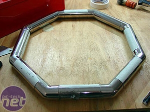
The frames beginning to take shape. The aim was for them to assemble, with tight joins and no bending or forcing required. Fortunately, the whole 'measure twice, cut once' philosophy worked.


With the frames together, I securely taped all the joins and covered each side with tape. This was to give me a surface to mark for drilling and, at this point, the tape was all that was holding them together.


I made a template (drawn in Illustrator and stuck to cardboard) to give me an accurate centre-mark for the pipe. Each piece of pipe had to be marked for the M4 screws to hold it to each elbow, plus the two M6 holes for the brackets.


I made another template to draw the holes for the brackets. Once marked, a centre-punch indented each hole position to stop the drill bit slipping.


3.2mm holes were drilled with the drill press. A board clamped to the drill table supported the frames and kept them at 90-degrees to the drill bit.

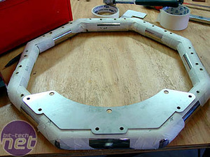
The template helped me mark the holes for the brackets. These were drilled 5mm and tapped to M6 threads.
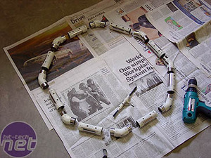

To tap the M4 holes for the screws to hold the elbows, I disassembled the frames and tapped the pipe and elbow separately, not together. I did this after breaking a couple of taps and spending hours trying to get the broken pieces out of the holes.
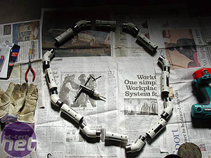
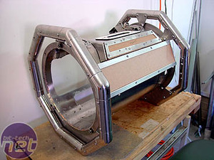
After all the holes were threaded, the frames were glued with 24-hour epoxy, the small screws at the elbows being screwed in while the glue was still wet.

MSI MPG Velox 100R Chassis Review
October 14 2021 | 15:04



Want to comment? Please log in.