Foxconn WinFast NF4K8AA-8EKRS Features:
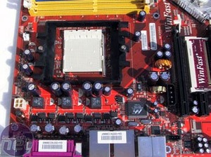
- Support for all AMD Althon 64 Socket 939 Processors with 2000MT/s HyperTransport Interlink;
- NVIDIA nForce 4 SLI chipset;
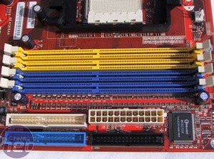
- Four PC3200 DDR DIMMs (2.5v, 184-pin, 4GB max);
- Ten USB 2.0 ports;
- Two IEEE Firewire ‘a’ (400MBit) ports;
- Four SATA2 ports with 300MBit and NCQ support;
- Two ATA133 IDE ports;
- NVIDIA RAID 0, 1, 0+1, JBOD across Serial and Parallel ports;
- Two SATA ports on Silicon Image 3132 RAID controller with support for RAID 0 and 1;
- One Marvell PCI-Express x1 and one NVIDIA Gigabit Ethernet ports;
- 8-channel audio from Realtek’s ALC850 audio chip with RCA digital and optical S/PDIF outputs;
- Two PCI-Express x16, one PCI-Express x1, three legacy PCI expansion slots.
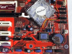
As a general rule of thumb all the major components are easily accessible and well laid out towards the edges of the board. The 24-pin ATX power connector is backward compatible with older 20-pin models, so you’ll be able to use your existing power supply provided that it is powerful enough.


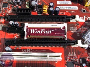
The mini-PCB for selecting between normal (16x1) and SLI (8x2) mode of the PCI-Express x16 slots is pretty fiddly and very close to the lower PCI-Express x16 slot. You’re also more likely to loose a little PCB rather than a fully integrated digital switch however an average user is likely to change it only a couple of times in the boards lifetime and it’s very securely held in, so unless you have fat fingers or no nails it isn’t really an issue.

MSI MPG Velox 100R Chassis Review
October 14 2021 | 15:04


Want to comment? Please log in.