Traditional Pipelines:
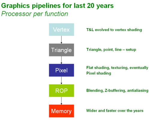
In order to explain the design decisions that NVIDIA made when it designed the architecture for its GeForce 8800 graphics processor, we need to go back over the way that the traditional graphics pipeline has worked in the past. The easiest way to explain this is to follow the data from the CPU into the GPU and then through the various stages of processing until the pixel appears on the screen.The first stage in the graphics pipeline is the vertex stage – this starts when the CPU sends the vertex data to the GPU ready for processing. Back in the days of DirectX 7, the vertex data was handled by fixed-function transform and lighting hardware; it wasn’t until DirectX 8 that we finally had programmable vertex shaders. DirectX 9.0 expanded on this with programmable pixel shaders (in Shader Model 2.0) and then introduced dynamic flow control in DirectX 9.0c (Shader Model 3.0).
Dynamic flow control essentially removes some of the CPU overhead when utilised, because it allows the graphics pipeline to skip parts of the shader that don’t need to be executed. Developers can use dynamic flow control to execute different paths through the same shader programme on adjacent pixels. The feature also helps to avoid state change overhead by combining multiple shaders that are similar into a single instruction.

With a DirectX 10 programme, it’ll be possible to push physics simulation, tessellation and interpolation of the hair algorithm into the GPU – this is obviously going to remove the dependency for a fast CPU, because the GPU is going to spend less time waiting for the CPU to execute large portions of algorithms.
Following the vertex stage, the vertices move on to the Setup stage – this is where the vertices are assembled into triangles, lines and points. These primitives are then converted into pixel fragments during the rasterisation stage, but they’re not full pixels at this stage in the pipeline – they can’t be referred to as pixels until they have finally been written to the frame buffer.


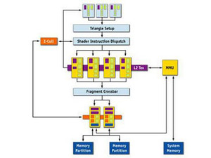
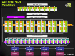
Examples of traditional graphics pipelines (NV44 / G70)
Once the pixel fragments with colour and Z values have been through the pixel shader, they move on down to the ROP (Raster Operations or pixel output engine) stage of the pipeline. This is where the Z-buffer checks all pixel fragments to ensure that only visible pixel fragments continue their journey through the ROP. The remaining pixel fragments are then blended with existing frame buffer pixels if they are partially transparent before being anti-aliased. Finally, the finished pixel is sent to the frame buffer in readiness for displaying on your screen.

MSI MPG Velox 100R Chassis Review
October 14 2021 | 15:04


Want to comment? Please log in.