Under the heatsink:
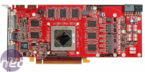
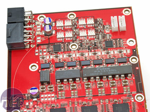
Following on from the Radeon X1950 Pro, AMD has again used a digital PWM controller on the Radeon HD 2900 XT. The card features a seven phase PWM array that’s made up of three different Pulse inductors coupled together (PA1314NL, PA1312NL and PA0511).The inclusion of a digital PWM controller should mean a longer lifespan, finer voltage adjustments along with being able to withstand much higher temperatures than a conventional PWM controller – it also helps to save PCB space, too. The other thing to note about the board is the lack of capacitors – there are only three solid aluminium capacitors on the entire card. This is a direct result of AMD using a digital PWM on the card.
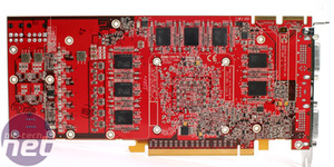
The Radeon HD 2900 XT comes complete with sixteen Hynix 32MB GDDR3 modules, making a total of 512MB of on-board memory. There are eight chips on each side of the PCB, which are arranged in a three-three-two horseshoe.
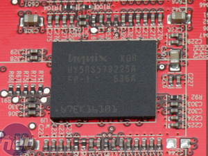
After putting the DRAM chip’s code through the Hynix chip decoder, we were able to work out that they’re rated to 1.0GHz (2.0GHz effective) with a 1.8V VDD/VDDQ. There are additional specifications too, but they’re mostly beyond the scope of this article.
One thing we can establish is that these chips are rated to 1000MHz (2000MHz effective), but are only clocked at 825MHz (1650MHz effective). This means that there should be a lot of overclocking headroom in them.
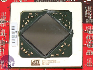
Notice that the R600 chip on the board is rotated by 45 degrees to make room for the card’s 512-bit memory bus width. Interestingly, there are no etchings in the chip’s surface – instead the chip’s details are laser cut into the shim on the chip’s packaging. The chip we’ve photographed here was manufactured in week 11 of this year – sometime in the middle of March, in layman’s terms. Another thing that you can’t quite see from this picture is that the shim is actually slightly higher than the chip’s surface.
Strangely, there are two 4-pin fan headers. Only one of these is used with the stock heatsink/fan design, so maybe the second fan header is something to do with the cooling solution on the ‘prototype’ R600 cards that were floating around on the web.
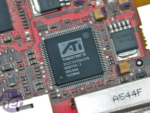
Finally, the card uses the familiar ATI Theater 200 video capture chip, which is located next to the bottom DVI port. For those not familiar with the chip, it essentially adds VIVO capabilities to the card via two components, namely a video decoder and an audio processor. The video decoder is able to handle simultaneous analogue inputs while the audio processor can process sounds up to a 16-bit 96KHz output.

MSI MPG Velox 100R Chassis Review
October 14 2021 | 15:04




Want to comment? Please log in.