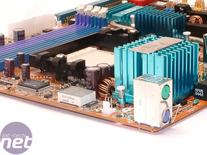
Along the right hand edge of the motherboard there is the POST code readout display and ABIT's µGuru chip. There is a list of POST code readout definitions in the manual. Interestingly, the µGuru chip package has changed since we reviewed ABIT's AN8-SLI motherboard last December. µGuru enables users to have real-time monitoring and tweaking facilities available to them at the click of a mouse. There are four small applications that form the µGuru suite: ABIT EQ, OC Guru, FlashMenu and BlackBox. You can read more about these on ABIT's home page.
 We had some issues getting FlashMenu working correctly - we think this is related to the fact that there aren't any updated BIOS revisions available. However, it didn't tell us that this was the case. Instead, it told us that our version of FlashMenu was out of date and that we needed to get the latest version from the ABIT FlashMenu website. We downloaded the latest version from the website and installed it, only to get the same problem. We think this is a bug in the software and we hope that ABIT addresses it soon. Currently, the program comes across as a bit of an endless loop - it'd be much easier if ABIT told the end user that there weren't any newer BIOS revisions, rather than sending them off on a wild goose chase.
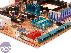
The 24-pin ATX power connector is conveniently located on the upper portion of the bottom edge of the motherboard next to the mounting hole near to the middle of the edge. The two ATA133 ports are in the left hand portion of the board on the bottom edge. They have also been rotated 90 degrees to improve cable management.
In the bottom left-hand corner of the board, there are several components in close proximity of each other. Right in the corner, there is a red pin header for connecting the Guru Clock to. However, as noted, there isn't a Guru Clock included in the AN8 32X's bundle. Above that, there is the front panel pin headers for power and reset switches, LED indicators and the system speaker. The CMOS reset switch is located just above that.
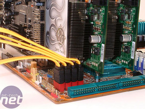
 Moving in from the edge of the board a little, there are four SATA II ports controlled by the NVIDIA nForce4 disk controller, the BIOS chip, and three USB pin headers (coloured blue). We thought that there would be problems installing four SATA cables with two GeForce 7900 GTX's installed - it's very tight but ultimately possible to run four SATA devices off the NVIDIA disk controller. Next to the bottom PCI slot, there is a red pin header for IEEE1394 Firewire - this has support for the IEEE 1394a specification. There are three yellow jumpers located just below the IEEE 1394 pin header - when switched, they give the three USB pin headers wake-up functionality.
ABIT has used the Winbond W83627EHG I/O controller chip - this is located in the top left hand edge of the board, next to the second PCI expansion slot. Moving further along the top edge of the board, there is the Realtek ALC850 AC'97 audio codec, along with a front panel audio header and a single internal CDROM-style audio connector.
The two PCI-Express x16 slots have an interesting clip-release mechanism - the clip for releasing the video card is on the outer edge of each port. While this is a great idea in principle, we found it a little tough to remove a GeForce 7900 GTX from the bottom slot - that problem is going to be even more apparent when the board is fitted inside a chassis, as you don't have the freedom to move the board around to solve the problem of removing a card with a dual slot cooler.
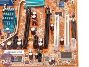
 Putting the release mechanism on the opposite side of the secondary slot would have solved this problem, but it would have created another problem, too. You'd need to remove the card in the primary slot before it's possible to remove the card in the secondary slot with the clip on the opposite side. Don't get me wrong, this is a nice idea and one of the best PCI-Express x16 clip mechanisms I've used. It comes unstuck because there is only a single slot between the primary and secondary PCI-Express x16 interconnects.
For many people, this will not be an issue as they're not constantly swapping components in and out of motherboards. Another thing worth noting is that we really like the fact that ABIT has put additional power circuitry between the two x16 interconnects to ensure that the power delivered to the two slots is as clean as possible.
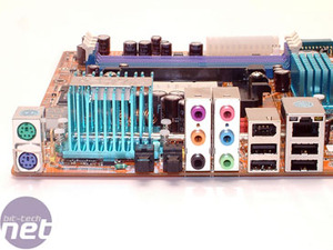
At a glance, the back panel looks pretty bare. However, the only things missing are the legacy ports that very few people use these days. There are two PS/2 ports, four USB2.0 ports, a 6-pin IEEE 1394a Firewire port, six audio jacks, optical S/PDIF-In and S/PDIF-Out ports and a single Gigabit Ethernet port controlled by the Vitesse VSC8201 PHY Gigabit Ethernet controller.
This board is targetted at enthusiasts so it's good to see that ABIT has decided to use a back I/O panel that is free from legacy ports. ABIT has been doing this for a while and it's about time more manufacturers grasped this trend on their enthusiast-orientated motherboards - Sapphire is one manufacturer that has adopted this approach with its Pure Innovation products.


The 24-pin ATX power connector is conveniently located on the upper portion of the bottom edge of the motherboard next to the mounting hole near to the middle of the edge. The two ATA133 ports are in the left hand portion of the board on the bottom edge. They have also been rotated 90 degrees to improve cable management.
In the bottom left-hand corner of the board, there are several components in close proximity of each other. Right in the corner, there is a red pin header for connecting the Guru Clock to. However, as noted, there isn't a Guru Clock included in the AN8 32X's bundle. Above that, there is the front panel pin headers for power and reset switches, LED indicators and the system speaker. The CMOS reset switch is located just above that.


ABIT has used the Winbond W83627EHG I/O controller chip - this is located in the top left hand edge of the board, next to the second PCI expansion slot. Moving further along the top edge of the board, there is the Realtek ALC850 AC'97 audio codec, along with a front panel audio header and a single internal CDROM-style audio connector.
The two PCI-Express x16 slots have an interesting clip-release mechanism - the clip for releasing the video card is on the outer edge of each port. While this is a great idea in principle, we found it a little tough to remove a GeForce 7900 GTX from the bottom slot - that problem is going to be even more apparent when the board is fitted inside a chassis, as you don't have the freedom to move the board around to solve the problem of removing a card with a dual slot cooler.


For many people, this will not be an issue as they're not constantly swapping components in and out of motherboards. Another thing worth noting is that we really like the fact that ABIT has put additional power circuitry between the two x16 interconnects to ensure that the power delivered to the two slots is as clean as possible.
At a glance, the back panel looks pretty bare. However, the only things missing are the legacy ports that very few people use these days. There are two PS/2 ports, four USB2.0 ports, a 6-pin IEEE 1394a Firewire port, six audio jacks, optical S/PDIF-In and S/PDIF-Out ports and a single Gigabit Ethernet port controlled by the Vitesse VSC8201 PHY Gigabit Ethernet controller.
This board is targetted at enthusiasts so it's good to see that ABIT has decided to use a back I/O panel that is free from legacy ports. ABIT has been doing this for a while and it's about time more manufacturers grasped this trend on their enthusiast-orientated motherboards - Sapphire is one manufacturer that has adopted this approach with its Pure Innovation products.

MSI MPG Velox 100R Chassis Review
October 14 2021 | 15:04


Want to comment? Please log in.