
Asus Striker Extreme Overview:
- Support for all Intel LGA775 processors, including Pentium 4, Pentium D, Pentium Extreme Edition, Core 2 Duo and Core 2 Extreme (including QX6700);
- NVIDIA nForce 680i SLI chipset
- Northbridge: NVIDIA C55-SLIX16N-A2;
- Southbridge: NVIDIA NF590-SLI-N-A2 (MCP55);
- Support for up to 8GB of DDR2-533, DDR2-667 or DDR2-800MHz memory, with additional support for NVIDIA SLI-Ready Memory up to 1200MHz;
- Two PCI-Express x16 slots for SLI (blue, running at x16) and one PCI-Express x16 slot (white, running at x8), one PCI-Express x1 slot and two PCI slots;
- Asus SupremeFX Audio Card with 7.1 channel support via ADI1988B HD Audio codec, complete with jack sensing, multi-streaming, jack-retasking and noise filter, along with co-axial and optical S/PDIF out ports;
- Dual Gigabit Ethernet PHY via a pair of PCI-Express based Marvell 88E1116-NNC1 network controllers;
- Six native SATA 3Gbps ports supporting RAID 0, 1, 0+1, 5 and JBOD;
- Two eSATA 3Gbps ports supporting SATA-on-the-Go (on rear I/O panel);
- Support for ten USB 2.0 ports (four on rear I/O panel, six via on-board pins/expansion brackets);
- Two IEEE1394a Firewire ports (one on rear I/O panel, one via on-board pins/expansion brackets);
- One ATA133 connector and one floppy connector.
Layout:

Click to enlarge
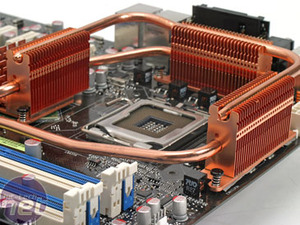
The colour scheme for the board stands out – Asus has stuck to blue and white components virtually all the way across the black PCB, with only a few components using a different colour. You could argue that the dominant force on the motherboard is the huge copper heatsink assembly that surrounds the CPU socket and covers both north and south bridges – it certainly fills a large area on the board.
Asus has designed the heatsink in a way that allows the board to run completely silent without the need for active cooling on the board itself. However, Asus has sent us a preliminary bundle of what is likely to come with the final retail product, and that bundle includes a fan – it’s similar to the one we saw on the Asus A8N32-SLI Deluxe towards the back end of last year. We assume that this is for when you’re watercooling the CPU, because there won’t be any air flowing across the heatsinks.
While the area around the CPU socket is clear and there’s plenty of room to install more exotic cooling solutions, the layout of the heatsinks surrounding the CPU socket will prevent some of the larger heatsinks from fitting on the board without modification. If your heatsink is wider than 103mm less than 35mm from its base, there will not be room.
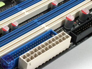
The other niggle we have with the layout is the positioning of the ATA133 connector – it’s directly behind the 24-pin ATX power connector, making it a bit of a pain to route the cables neatly. It would have made more sense to put the floppy connector there instead, because that’s likely to inconvenience fewer people, strictly speaking.
Moving around the board, there are six 3-pin fan headers that, with the exception of the one by the bottom PCI-Express x16 slot, are in accessible positions. These fan headers are on top of the 4-pin fan header for the CPU fan – that’s located to the right of the memory slots in our plan view of the board.


MSI MPG Velox 100R Chassis Review
October 14 2021 | 15:04

Want to comment? Please log in.