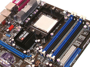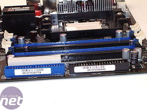
Interestingly, there's no need for an additional four-pin molex connector when using the board in dual-card mode. The supplementary power connector was required on the ASUS A8R-MVP and it was required on ASUS' range of SLI motherboards, too. Also, it's interesting to see that ASUS hasn't adopted the new 8-pin 12v power connector that is starting to replace the 4-pin 12v connector that has been a permenant fixture on all motherboards since the changes that were made to power requirements when the Pentium 4 launched all those years ago.
The area around the CPU socket is clutter free too. We had no problems installing large heatsinks as there aren't any large and intrusive capacitors surrounding the CPU socket. The same is true for the memory and video card slots too. One of the major problems with the ASUS A8N32-SLI Deluxe was that it was impossible to reset the CMOS jumper without removing the bottom video card from the board. We're glad to see ASUS has addressed this problem on the A8R32-MVP, as it's possible to reset the CMOS jumper without removing the bottom video card from the board.


The memory slots are coloured according to memory channel - it's possible to populate the motherboard with four DIMMs running at 400MHz 2.0-2-2-7 with the slightly slower 2T command rate. With only two DIMMs placed in either the blue or black slots, it's possible to run the same timings and frequencies with a 1T command rate.


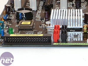
Rather than rotating one of the IDE connectors 90 degrees, as was featured on the A8N32-SLI, ASUS has decided that the floppy connector gets the rotation treatment on the A8R32-MVP. It would have been nice to see the two IDE connectors rotated through 90 degrees too, because we feel that it can help with cable management.
The four SATA II connectors controlled by the ULi M1575 South Bridge are just to the right of the floppy connector, directly below the South Bridge chip. They're out of the way of the secondary PCI-Express x16 interconnect, meaning that longer video cards, like ATI's Radeon X1900XT and X1900XTX will not get in the way of SATA cables connected to the board.

MSI MPG Velox 100R Chassis Review
October 14 2021 | 15:04


Want to comment? Please log in.