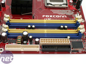
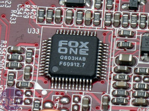
The 24-pin ATX power adapter is located next to the DDR2 memory slots along the bottom edge of the motherboard. Both the floppy connector and the lone ATA133 IDE connector are also in the same area of the board too. Foxconn's all-new Fox One chip is located to the left of the memory slots - we'll explain how this works shortly.
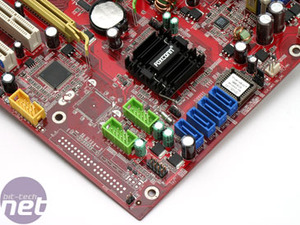
 Along the bottom edge of the board, the CMOS reset switch, BIOS chip and four SATA ports are all next to each other in a line. The SATA ports are all controlled by the ICH7R south bridge's internal disk controller. The controller has support for RAID 0, 1, 5, 10 and JBOD disk configurations.
There are two USB 2.0 pin headers to the left of the SATA ports and south bridge. These are colour coded so that end users can work out what should be plugged into where. The headers have a shroud too, making it easier to align the plug up correctly. However, one thing that Foxconn didn't do was to colour code the plugs on the expansion brackets too. It would have made sense for this to be done, as it is clear that Foxconn has attempted to make the installation process as simple as possible.
 The headers for the front panel case connections are located near to the bottom left hand corner of the board. Along the left hand edge of the board, there are soldering points for an additional ATA133 connector and also a surface mounted chip. Foxconn offers a version of this board with the additional ATA133 connector installed on the board. It's controlled by the Vasstek VSC6110 disk controller that enables support for the pioneer RAIDm1 (Reliable Access In a Disk by Mirror 1) specification.
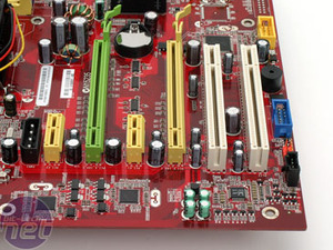
Next to that there is a pin-header for the IEEE 1394a Firewire expansion bracket. The on-board PC speaker and front panel pin header for an in-case PC speaker are located under the bottom PCI slot. The on-board speaker cannot be disabled. Moving further along the edge of the board, there is a pin-header for a serial port and also headers for front panel audio connections and CD-In. The problem with the serial port pin header is that Foxcon didn't include a serial port expansion bracket in the bundle.
With the CD-In and front panel audio connectors next to the bottom PCI slot, it is no surprise to see that the Realtek ALC882 High Definition Azalia audio codec is located next to the PCI slots. Much like all other Intel 975X retail motherboards we've seen, there are two PCI-Express x16 slots that are capable of supporting ATI's CrossFire technology; this runs with both slots using eight PCI-Express lanes. It appears that Foxconn is using a digital switching method in order to change the number of lanes available when two video cards are installed, similar to the one that MSI used on its P4N Diamond motherboard.
 There are two Marvell 88E8053 PCI-Express based Gigabit Ethernet controllers located next to each of the PCI-Express x1 slots. Finally, there is a lone SATA 300MBps port controlled by the Silicon Image 3132 controller located right next ot the 8-pin ATX 12v power connector. The second port controlled by the Sil3132 controller is located on the back I/O panel.
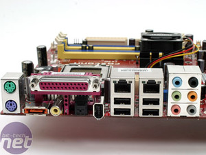
Speaking of which, the back I/O panel is nothing out of the ordinary. There is still a legacy parallel port included, but most printers these days use the USB interface. Of course, there is also a pair of PS/2 ports, four USB ports and two Gigabit Ethernet sockets. There are six universal audio jacks with jack sensing, along with both RCA and Optical S/PDIF ports and an IEEE 1394a Firewire port.


There are two USB 2.0 pin headers to the left of the SATA ports and south bridge. These are colour coded so that end users can work out what should be plugged into where. The headers have a shroud too, making it easier to align the plug up correctly. However, one thing that Foxconn didn't do was to colour code the plugs on the expansion brackets too. It would have made sense for this to be done, as it is clear that Foxconn has attempted to make the installation process as simple as possible.


Next to that there is a pin-header for the IEEE 1394a Firewire expansion bracket. The on-board PC speaker and front panel pin header for an in-case PC speaker are located under the bottom PCI slot. The on-board speaker cannot be disabled. Moving further along the edge of the board, there is a pin-header for a serial port and also headers for front panel audio connections and CD-In. The problem with the serial port pin header is that Foxcon didn't include a serial port expansion bracket in the bundle.
With the CD-In and front panel audio connectors next to the bottom PCI slot, it is no surprise to see that the Realtek ALC882 High Definition Azalia audio codec is located next to the PCI slots. Much like all other Intel 975X retail motherboards we've seen, there are two PCI-Express x16 slots that are capable of supporting ATI's CrossFire technology; this runs with both slots using eight PCI-Express lanes. It appears that Foxconn is using a digital switching method in order to change the number of lanes available when two video cards are installed, similar to the one that MSI used on its P4N Diamond motherboard.


Speaking of which, the back I/O panel is nothing out of the ordinary. There is still a legacy parallel port included, but most printers these days use the USB interface. Of course, there is also a pair of PS/2 ports, four USB ports and two Gigabit Ethernet sockets. There are six universal audio jacks with jack sensing, along with both RCA and Optical S/PDIF ports and an IEEE 1394a Firewire port.

MSI MPG Velox 100R Chassis Review
October 14 2021 | 15:04




Want to comment? Please log in.