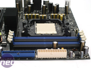
The 24-pin ATX power connector and lone IDE channel are along the edge of the motherboard, parallel to the four memory slots. The six SATA ports are arranged in a rather strange arrangement. Normally, SATA ports on the same disk controller are all placed right next to each other on the board.
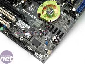
This can cause some issues, especially when using a pair of dual slot video cards in SLI or CrossFire mode, as the coolers on the video cards can often hinder some of the SATA connectors, reducing the amount of on-board disk connectivity. Foxconn has resolved this problem by rather intelligently splitting the locations of the SATA connectors into two areas.
Both areas of SATA ports are not hindered when a dual slot video card (or pair of video cards) are installed in the C51XEM2AA motherboard. One problem that we have is that Foxconn has chosen to use the older style SATA connections, rather than the new and much-preferred clip-lock connector.
Foxconn has used a passive heatsink on the north bridge and a small low profile copper fan on the south bridge. Next to the south bridge, there is a LED post code display - details of the code readouts are located in the back of the motherboard manual. There are a pair of USB 2.0 pin headers for the included expansion bracket or for front panel USB right next to the post code display.
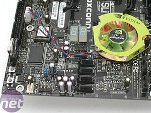 Moving closer to the bottom corner of the board, there is a single three-pin fan header - the only unused fan header on the motherboard. The front panel header for power, reset, and case LEDs is directly in between the single fan header and the bottom group of SATA ports. In the same area, there is the CMOS reset jumper and a pair of surface mount push switches for power and reset located next to the BIOS battery, which is perpendicular to the motherboard.
The floppy connector is next to the BIOS battery and both the BIOS and the three-pin fan header for the south bridge heatsink/fan are in close proximity; there is also a front audio pin header directly above the floppy connector.
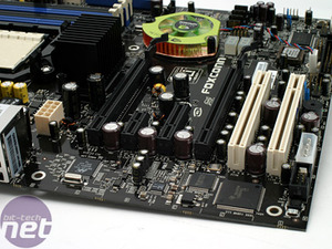
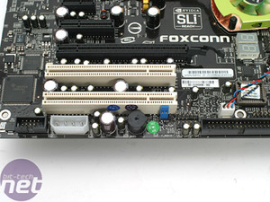 There are a pair of PCI slots, one of which is blocked when a pair of dual slot video cards are installed for SLI operation. Directly underneath the PCI slots, there is a system speaker with a jumper allowing you to turn it off if you don't want to hear POST and diagnostic beeps. As there is an LED post code display, there is not really much of a need for the speaker, so it can be disabled.
At the other end of the PCI slots, there is a lone four-pin molex connector. The manual suggests that this is recommended for use when a pair of NVIDIA video cards are installed for SLI operation in order to provide adequate power to the two PCI-Express x16 interconnects. The positioning of this is a little annoying. We said the same when we looked at Abit's AN8 32X nForce 4 SLI X16 motherboard - cable routing to this is a complete nightmare at the best of times.
 In between the two PCI-Express x16 slots, there are interconnects for PCIe x1 and PCIe x4 - the PCI-Express x1 interconnect is blocked when a dual slot video card is installed in the primary video card slot. Foxconn has used Realtek's ALC882D codec, giving the board Dolby Digital Live functionality and connectivity for external consumer devices; the chip is located right above the PCI-Express x4 interconnect.
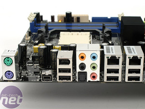
The back I/O panel has a pair of PS/2 ports, an IEEE1394b 'mini Firewire' port, a full-sized IEEE1394a Firewire port, six USB 2.0 ports, five analogue audio jacks, an optical S/PDIF out port and a pair of Gigabit Ethernet ports. These are both controlled by Marvell's 88E121 PCI-Express Dual Gigabit Ethernet controller and support all of NVIDIA's Networking Technologies.
This can cause some issues, especially when using a pair of dual slot video cards in SLI or CrossFire mode, as the coolers on the video cards can often hinder some of the SATA connectors, reducing the amount of on-board disk connectivity. Foxconn has resolved this problem by rather intelligently splitting the locations of the SATA connectors into two areas.
Both areas of SATA ports are not hindered when a dual slot video card (or pair of video cards) are installed in the C51XEM2AA motherboard. One problem that we have is that Foxconn has chosen to use the older style SATA connections, rather than the new and much-preferred clip-lock connector.
Foxconn has used a passive heatsink on the north bridge and a small low profile copper fan on the south bridge. Next to the south bridge, there is a LED post code display - details of the code readouts are located in the back of the motherboard manual. There are a pair of USB 2.0 pin headers for the included expansion bracket or for front panel USB right next to the post code display.


The floppy connector is next to the BIOS battery and both the BIOS and the three-pin fan header for the south bridge heatsink/fan are in close proximity; there is also a front audio pin header directly above the floppy connector.


At the other end of the PCI slots, there is a lone four-pin molex connector. The manual suggests that this is recommended for use when a pair of NVIDIA video cards are installed for SLI operation in order to provide adequate power to the two PCI-Express x16 interconnects. The positioning of this is a little annoying. We said the same when we looked at Abit's AN8 32X nForce 4 SLI X16 motherboard - cable routing to this is a complete nightmare at the best of times.


The back I/O panel has a pair of PS/2 ports, an IEEE1394b 'mini Firewire' port, a full-sized IEEE1394a Firewire port, six USB 2.0 ports, five analogue audio jacks, an optical S/PDIF out port and a pair of Gigabit Ethernet ports. These are both controlled by Marvell's 88E121 PCI-Express Dual Gigabit Ethernet controller and support all of NVIDIA's Networking Technologies.

MSI MPG Velox 100R Chassis Review
October 14 2021 | 15:04


Want to comment? Please log in.