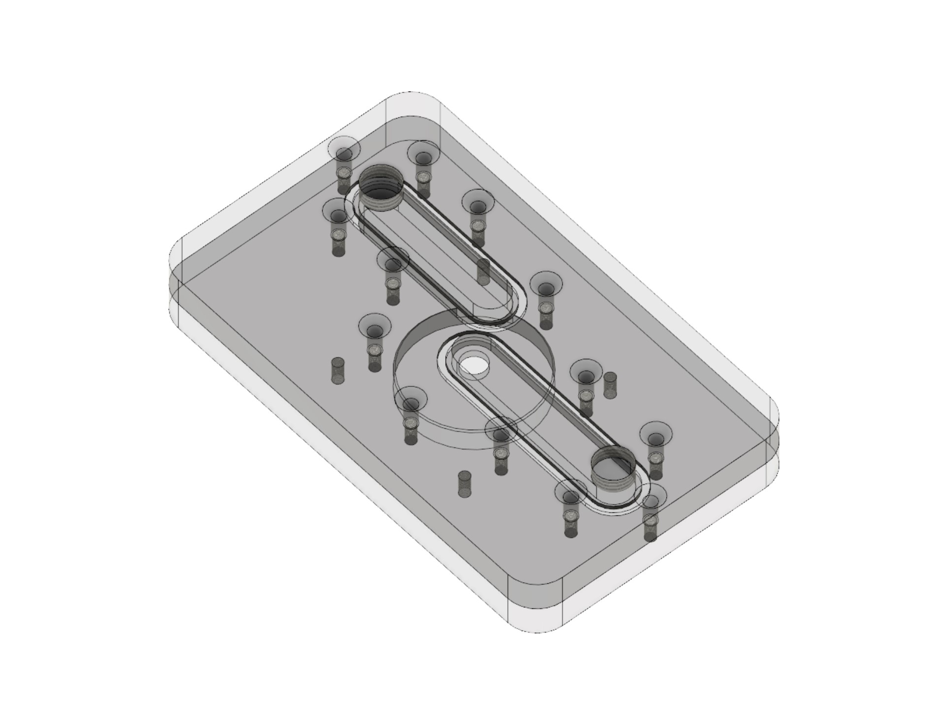
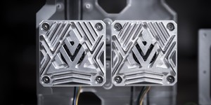
Now that we've had a look at some existing pump tops, it's about time we made our own. It makes sense to start with the DDC here since it's the simpler of the two. In the downloadable files, I've provided a copy of the model we're going to be making below. If Fusion 360 is new to you, I would suggest watching through the first Distro Plate Tutorial, as we'll be using many of the same techniques here.
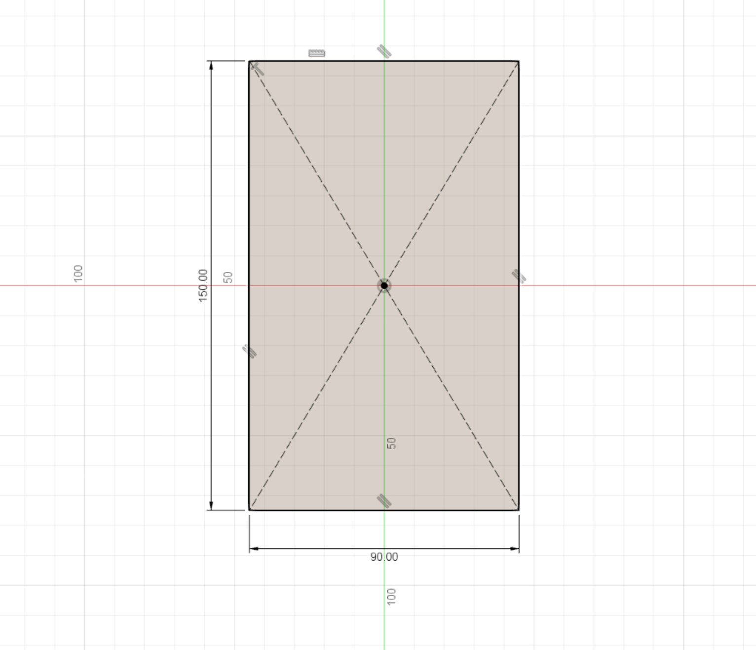
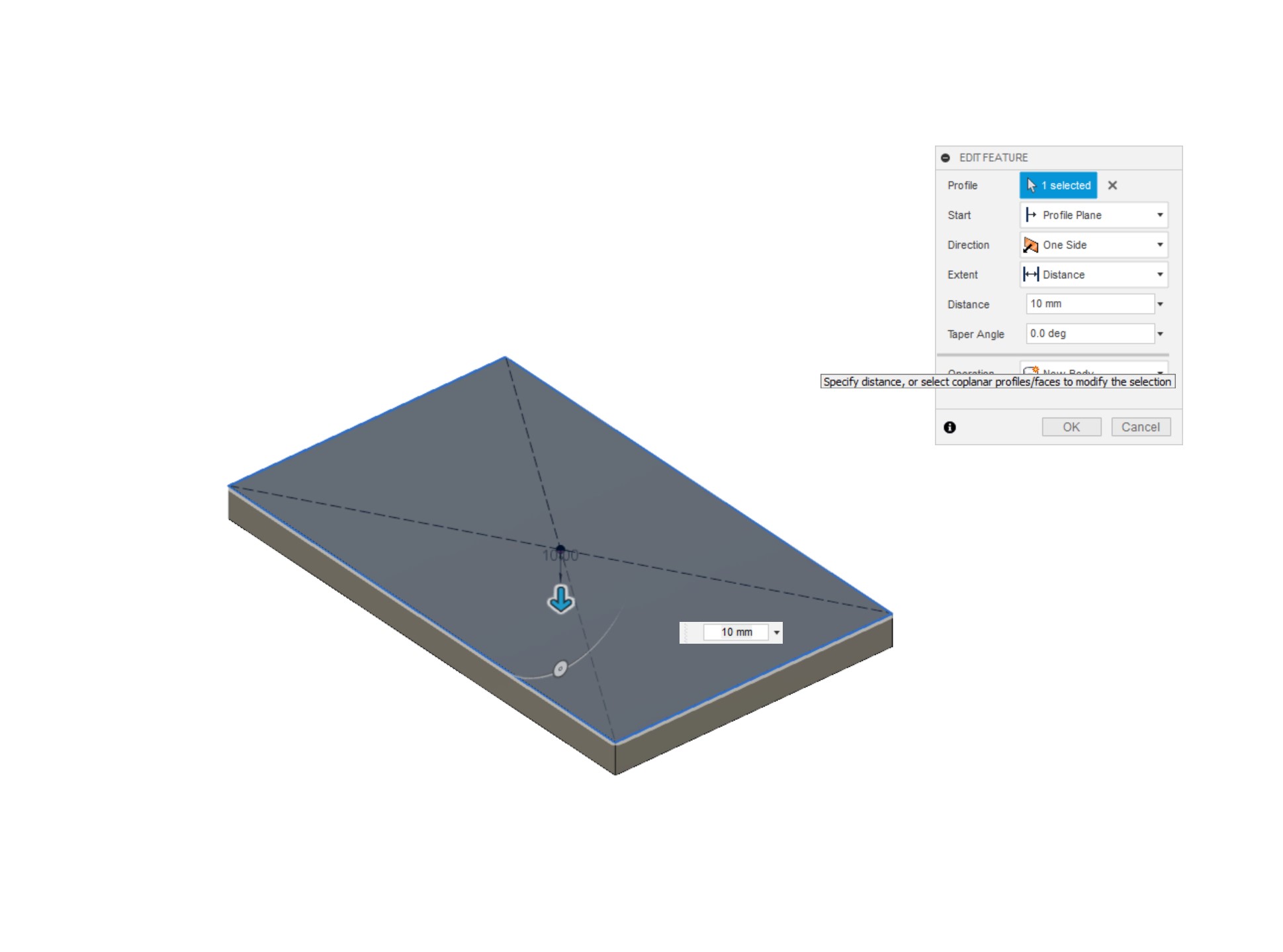
This is just a proof of concept model; you can of course tweak yours to fit your intended design. To start, we're going to create a new sketch and draw a 90x150mm rectangle with the centre rectangle tool. Where possible I like to work from the origin of the workspace, as it makes things easier later should you wish to use other commands like mirror or circular pattern. For this distro plate we're going to be using 2x10mm thick pieces of material. Of course you can adapt these measurements to your design, but I wouldn't go thinner than 10mm for either plate. Exit the sketch and extrude the rectangle to 10mm, selecting 'New Component' as you do it.
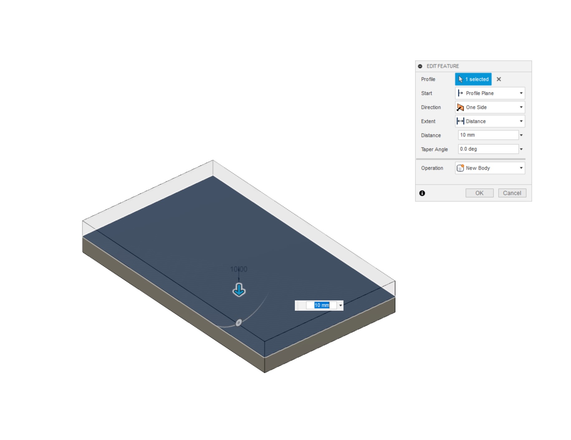
Next up we're going to add the rear plate; this is the one which the pump itself will mount into. Simply use the extrude tool again on the back face of the plate we just made, again clicking 'New Component' from the drop down menu, which will prevent it from simply making our existing plate thicker and instead form a new object. I do suggest labelling parts and sketches as you make them, as it makes it much easier to keep track of things as you go along, and should you send the file to somebody else,they will know what's going on too. I'm calling the first plate 'Front Plate' and the second one 'Rear Plate'.
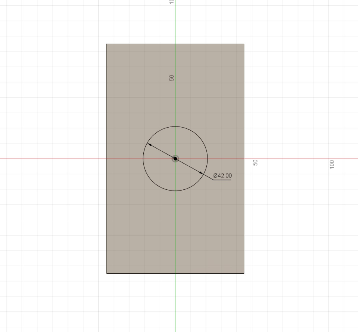
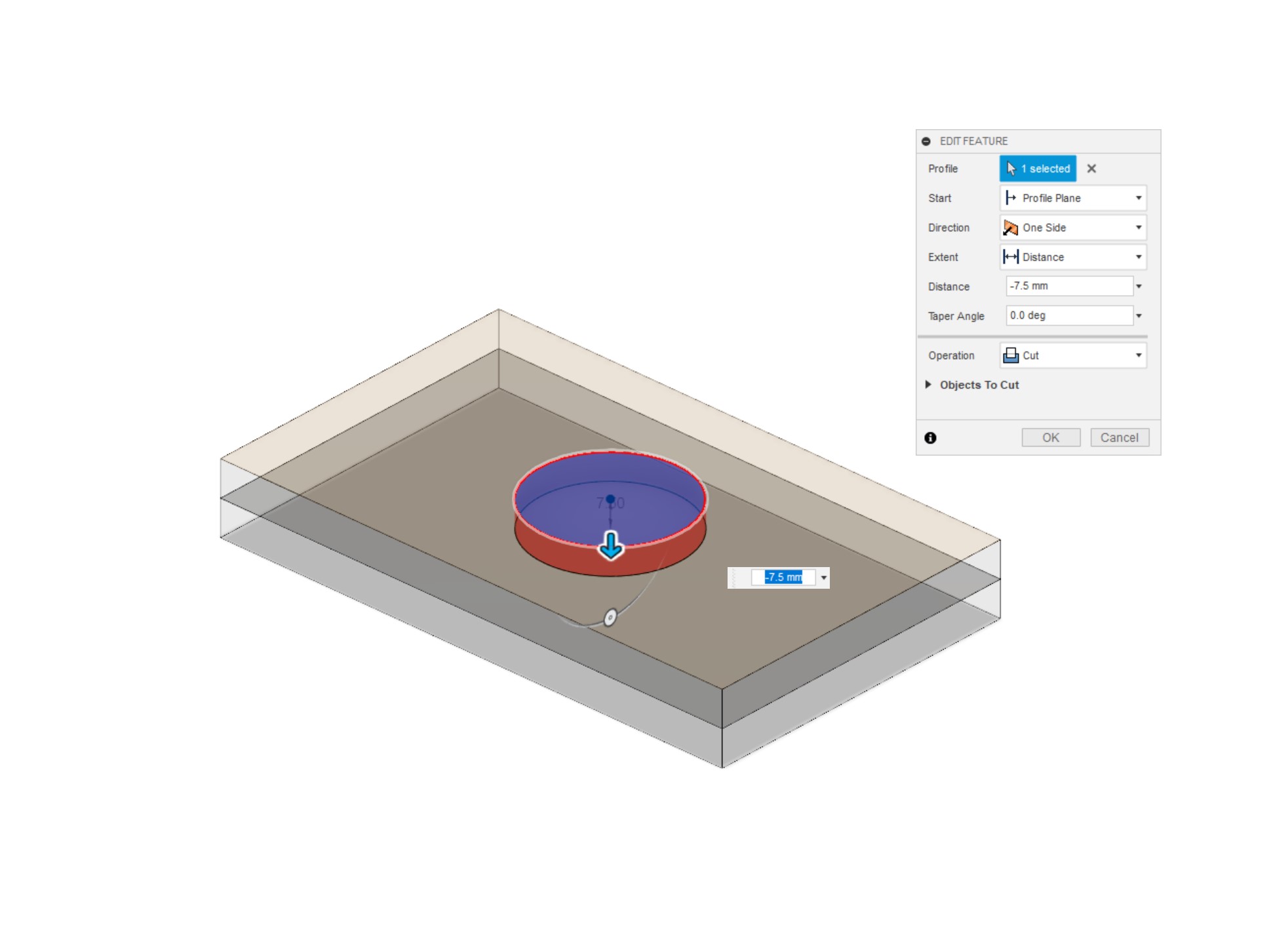
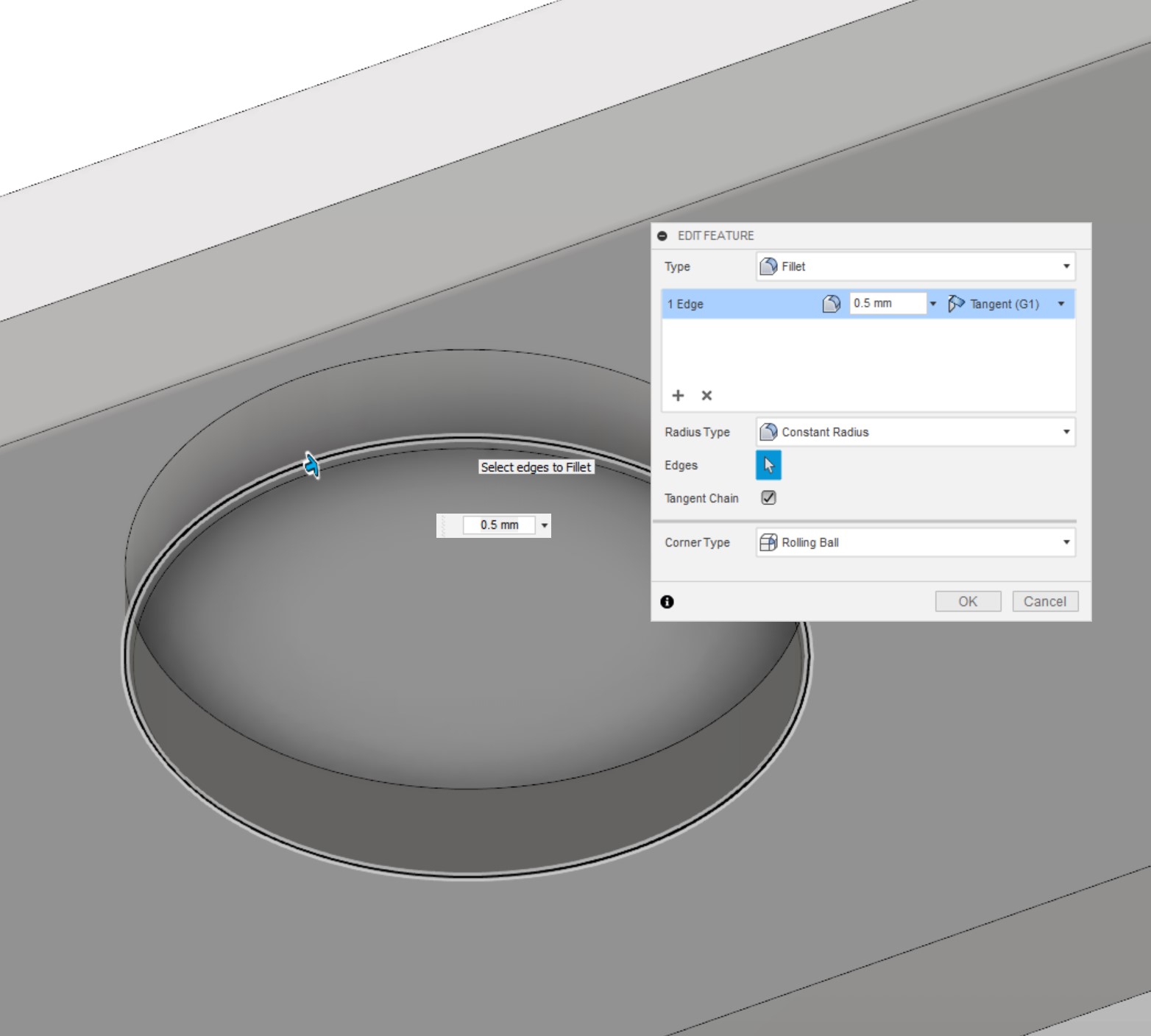
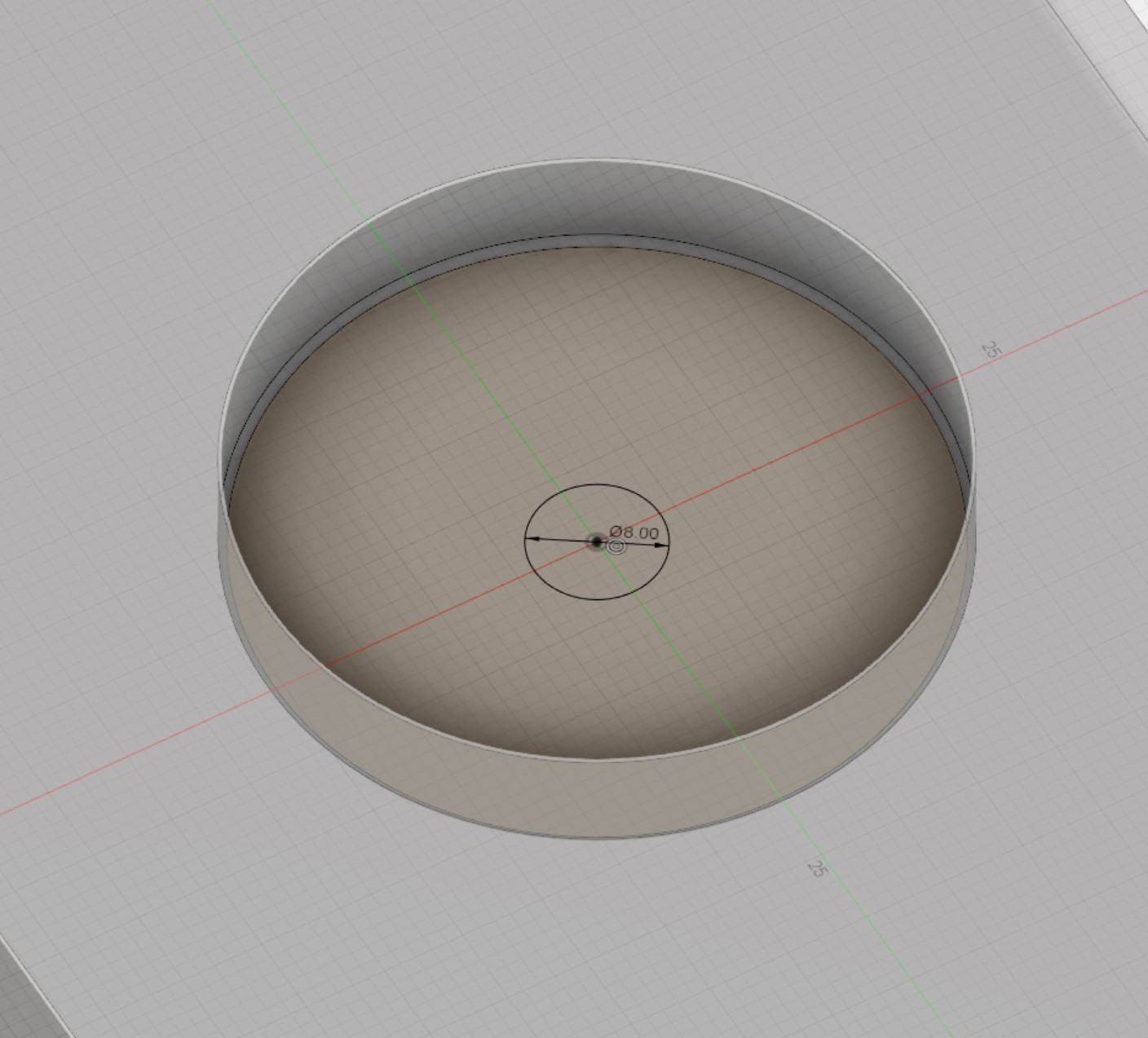
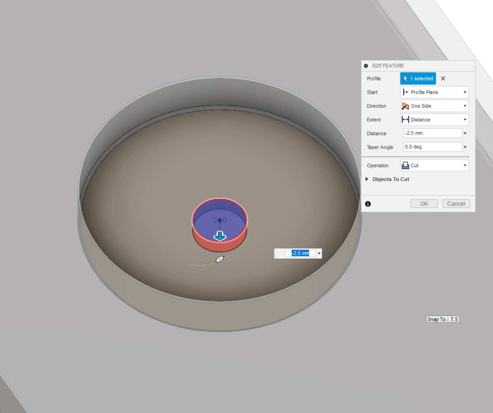
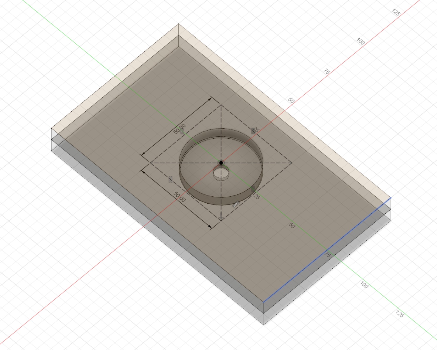
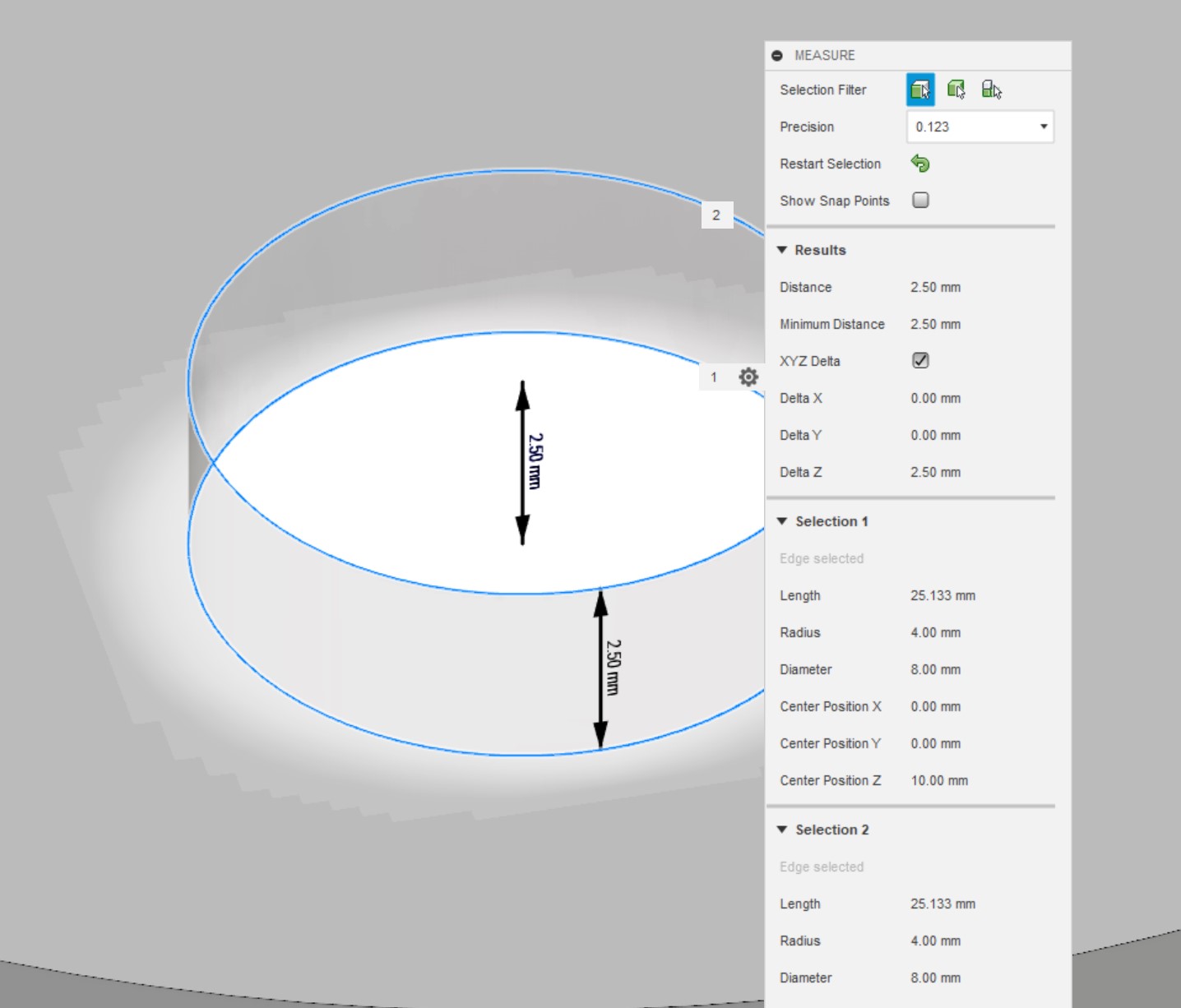
Now let's get into the meat of this top. Make a new sketch on the 'Rear Plate', then draw a 42mm circle in the centre of the sketch, this will become our impeller cavity. Exit the sketch, label, then extrude the circle down 7.5mm. We now have a cavity; you can optionally add a small 0.5mm fillet to the bottom edge of the cylinder, but that's not essential. Next create a new sketch on the base of the cavity, then draw another circle in the centre, this time 8mm in diameter. Extrude this smaller circle 2.5mm downwards to create the pump inlet hole.
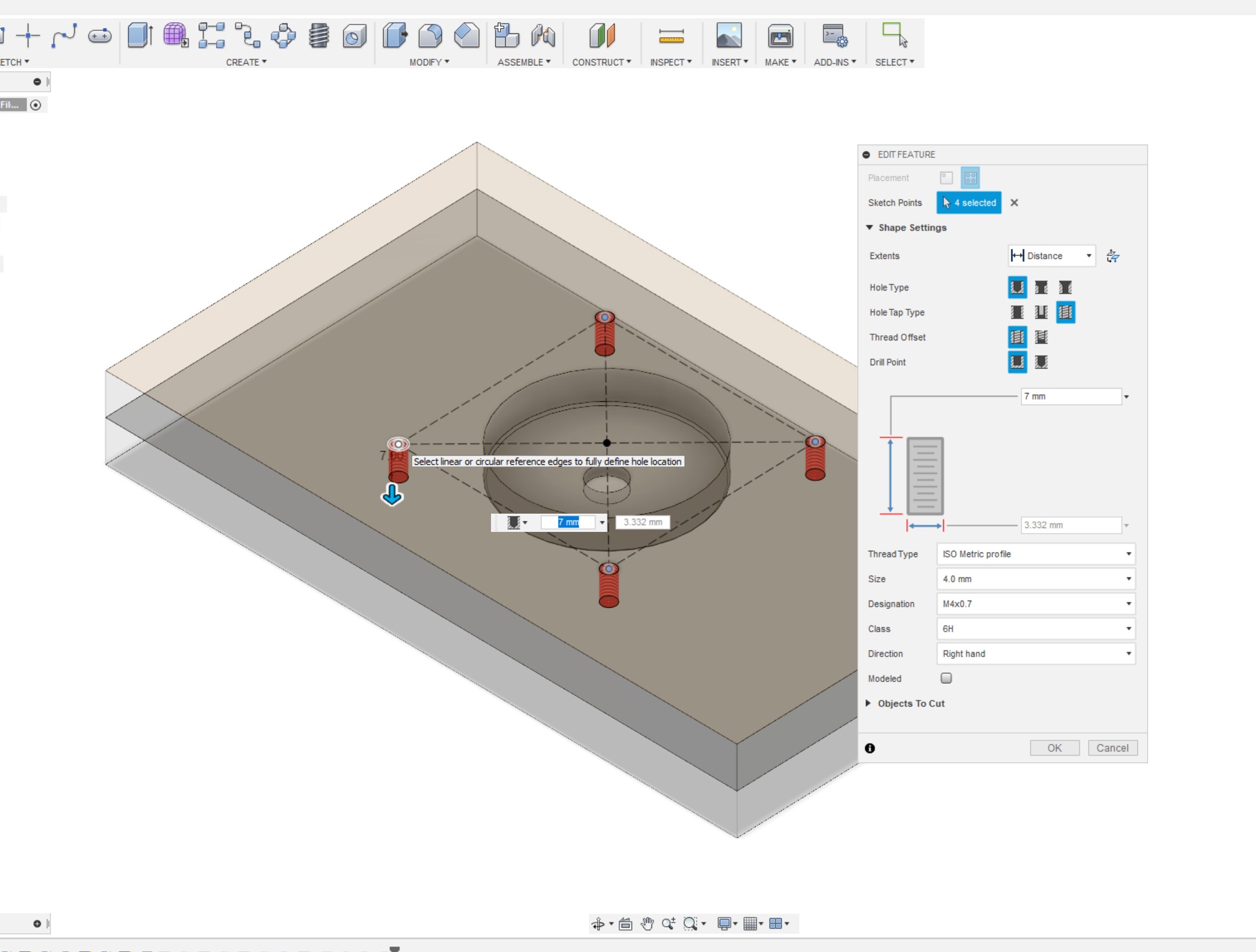
Since we have less control over how the DDC will mount to the plate compared to a D5, I like to add the mounting points now, as that way you can take them into account when adding the coolant channels. For the record, you'll find it easier to place the pump location in a distro first, then work out the channels after. The pump I'm using has 4xM4 screw holes spaced 50mm apart from one another in a square formation. Create a new sketch, then draw a construction line centre rectangle of 50x50mm from the centre of the inlet hole. Using the hole command, select the corners of the square to place 4 7mm deep M4 threaded holes. Our pump is now able to be mounted to the plate! I would 100-percent recommend double checking these measurements with the pump housing you intend to use, because there's no guarantee that they'll be the same.
We've got an inlet, so now that the pump mounts are added it's time to add an outlet. Personally the way I like to do this is by machining in from the other side of the 'Rear Plate', which means that the plate is a double-sided job but a pretty straightforward one. The orientation here is very important! If you view the pump from the front of a pump top, the impeller rotates anti-clockwise. As such, you want your outlet to be on the 'left' when viewing face-on. This means, counter-intuitively, that you want to draw it on the "right" hand side of the cavity in the following steps; the images and 3D file should hopefully keep that clearer.
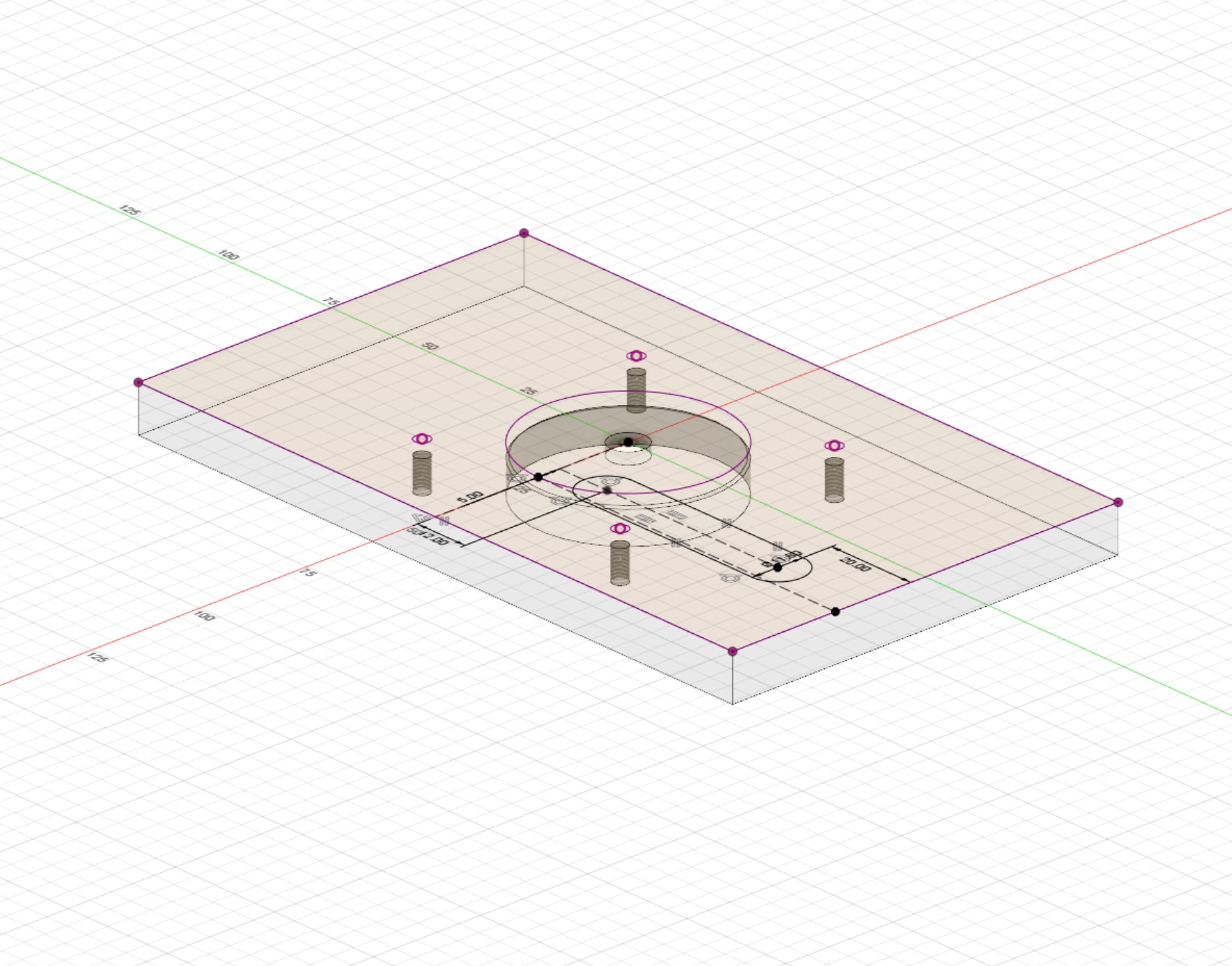
Toggle visibility for the 'Front Plate' and create a new sketch on the 'Rear Plate' on the opposite face to the cavity. In this sketch, project all the geometry modelled in so far - you want to know where everything is. Using the 'Centre-Centre Slot' tool, draw a slot from close to the cavity location to near to the bottom edge of the workpiece, make it 11.8mm wide (that's the same size as a G1/4 port). Constrain the slot so that it's vertical or parallel to the side of the workpiece, then place the bottom-most circle 20mm from that edge.
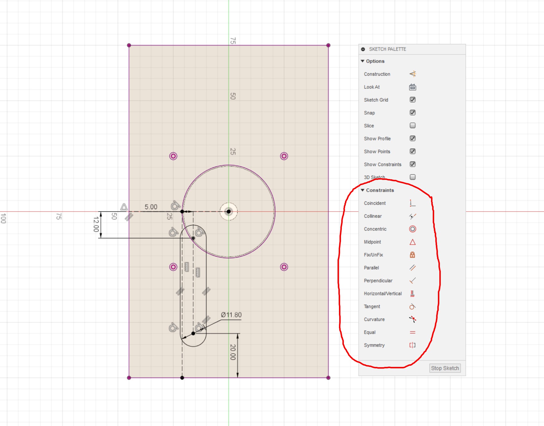
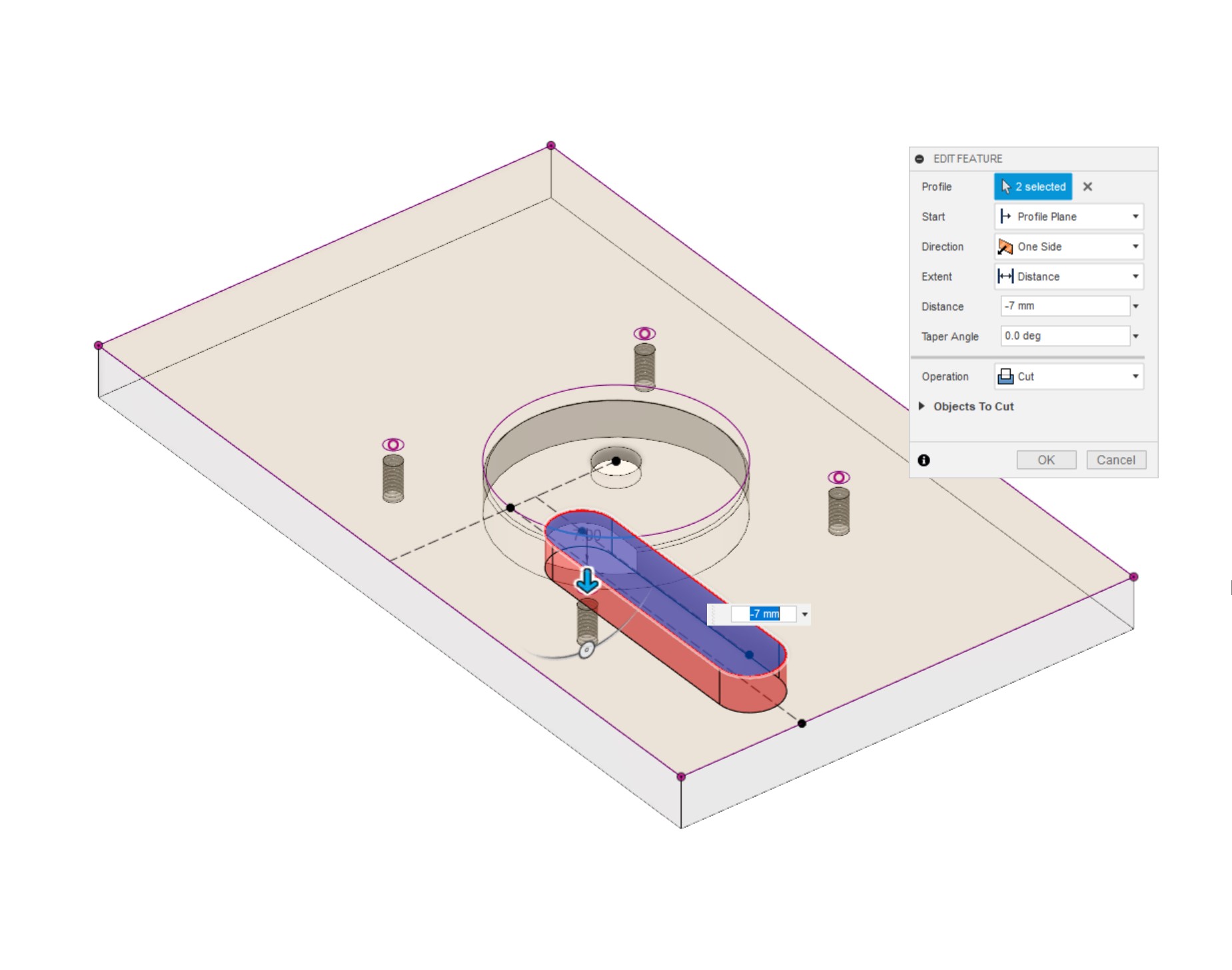
Draw a construction line from the centre of the cavity to the side - it must be perpendicular to the side edge. Next, draw another construction line from the edge of the cavity to the bottom edge, and constrain this line so that it's at a tangent to the cavity wall and also perpendicular to the bottom edge. Dimension the slot so that the centre line is offset 5mm from the long construction line; similarly, dimension the top of the slot so that it's 12mm below the centre construction line you drew. Exit the sketch, then extrude the channel we just drew 7mm downwards into the material. This will cut into the cavity, creating the outlet that the coolant will flow through.
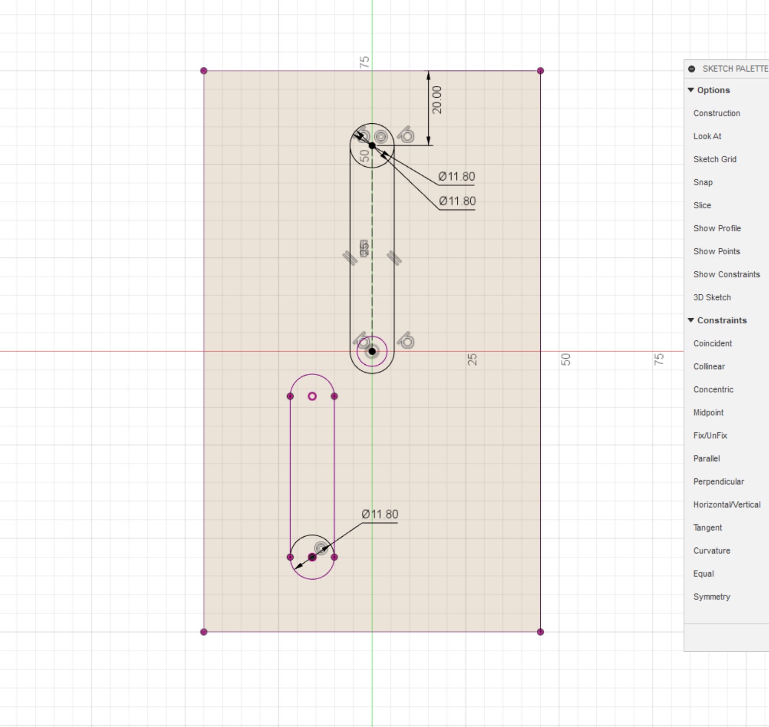
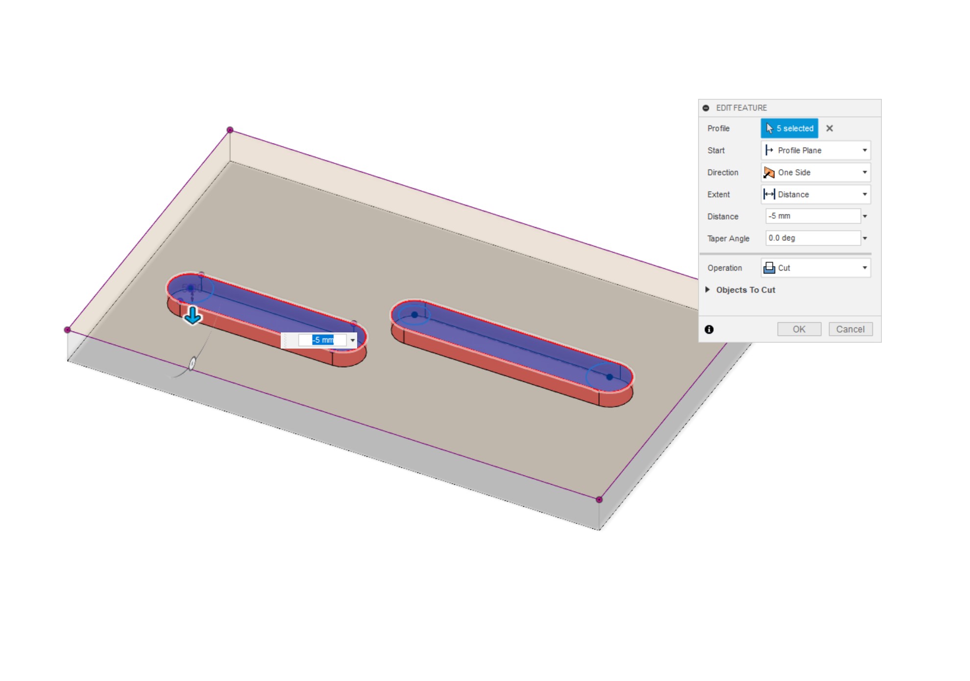
With the outlet modelled, all that's left to do is add the main channels themselves and make it all watertight. The channels will be cut from the front plate, so make that visible again and create a new sketch on the inside face. Like before, we want to know where everything we've modelled is, so use 'project geometry' to add the mounting holes, cavity and outlet/inlet to the sketch. Draw in where you'd like the inlet channel to flow from; I've gone with a very simple 11.8mm slot again that goes straight to the centre where the inlet port is located. Exit the sketch and extrude 5mm into the material - we now have our channels modelled. If working on a more complex distro, this point is where you would connect it up to the pump design.
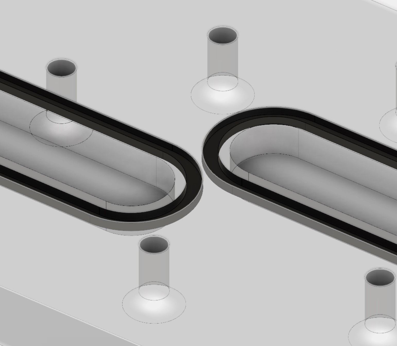
For the O-ring grooves, it's important that you cut them into the 'Front Plate', because there will be two O-rings in close proximity directly over the pump cavity. This part has been machined down, so the plastic is only 2.5mm thick, if you were to place an O-ring on that side it would mean the plastic is only 1.5-1mm thick, a risky proposition. Instead, put the O-rings in the thicker plate on the other side, that way the seal will be good and the plastic won't be put under too much strain. For the screws, follow the same steps as highlighted in the Distro Plate Article, placing them evenly around and making sure none of them conflict with either the pump cavity or the pump mounting screw holes!


MSI MPG Velox 100R Chassis Review
October 14 2021 | 15:04

Want to comment? Please log in.