Let's jump on the fan bus...
We started at the bottom with the castors and now we have reached the top of the case.The fanbus is a 4 channel electronic affair with press-on/press-off rotary speed controls. These controls are mounted on a sub chassis, which is bolted to the drive bay front panel. The control knobs are sunk into the panel and have then been drilled out to accommodate a red LED.
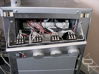
The front panel is backlit with blue neon string and all the front panel wires are connected to the circuit board via plugs and sockets to facilitate easy removal. Finally, the fanbus circuit board is mounted in a cut down 5.25" case from an old, busted CD drive.
Front removed showing control mounting chassis and cable connectors and modified CD case holding the circuit board.
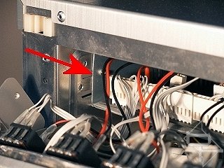
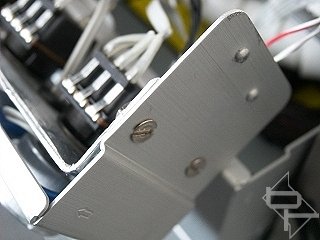
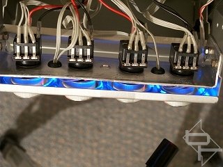
3mm nuts and bolts retain the control mounting plate. The front facing surface of the mounting plate was covered in chrome tape to reflect back the light from the neon string. This helped to give a very uniform lighting effect. Below you can also see the neon string lit (the string brightness was turned down to assist taking the photograph). The wires passing through the grommets connect to the leds in the control knobs.
A hole is drilled in knob for the LED which is push fitted into it.
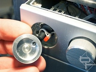

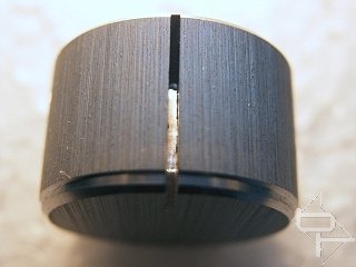
A close up showing how the drilled hole also opens the slit, which was previously blocked.
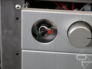
Before fitting the knob, turn the control shaft fully clockwise and wrap the led cable one turn clockwise around the shaft. This prevents the cable snagging when the knob is turned.

MSI MPG Velox 100R Chassis Review
October 14 2021 | 15:04


Want to comment? Please log in.