Setting up a Switchbay...
Problem: How do you take a set of front-panel switch and LED cables that end in 3.5mm jack plugs and interface them in an attractive way with the tiny wee pins on a motherboard?
Solution: Build a switchbay of course!
Here's how...
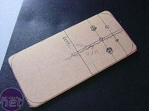
Taking a scrap piece of neon green perspex (once part of an earlier version of my VFD housing), I marked it up...
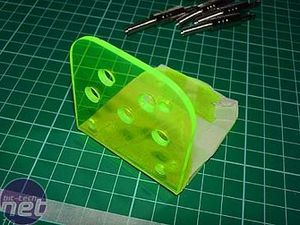
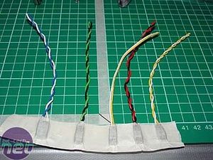
...and bent, filed, sanded, polished and drilled it and generally told it how naughty it was! I took some nasty coloured front-panel wires (my eyeeeeess!) cut the ends off and kept the headers, masked and...
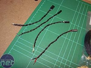
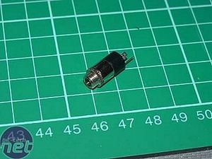
...vinyl dyed them black. Got a nice looking jack socket (mmmm...chrome end!) and...
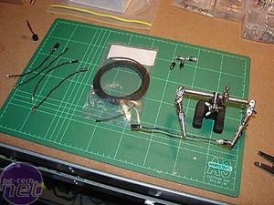
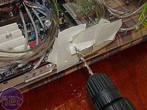
...soldered one socket onto each pair of front-panel wires. The whole lot were then sleeved in black Techflex nylon braid with the ends covered in black heatshrink. I test-fitted (again), marked and drilled some mounting holes.
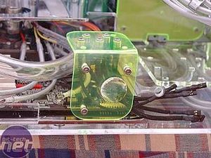
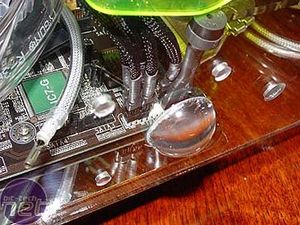
Checking the fit...and plugging in the headers. Even the piezo-type speaker got a coat of heatshrink.
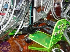
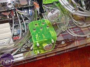
The wires were eventually folded in behind the switchbay and it was fixed in place with dome-nuts and washers. The cap-screws ended up the other way around. In my rush to get more things installed in the case I forgot to take a picture of the switchbay once all plugged in. Oh well, c'est la vie.
A word on Cable Management
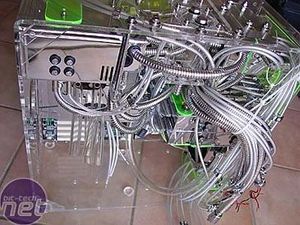
During the last parts of the project I was literally drowning in cables. I knew they would all terminate in some fashion at the end, but that didn't make it any easier to keep them all out of the way when fitting components. I resorted to making slings out of cable ties and gathering great bunches of the wiggly things to tie off to parts of the case, moving them periodically when I had to work on another section.
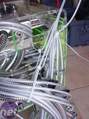
It seemed to work well.
Problem: How do you take a set of front-panel switch and LED cables that end in 3.5mm jack plugs and interface them in an attractive way with the tiny wee pins on a motherboard?
Solution: Build a switchbay of course!
Here's how...

Taking a scrap piece of neon green perspex (once part of an earlier version of my VFD housing), I marked it up...


...and bent, filed, sanded, polished and drilled it and generally told it how naughty it was! I took some nasty coloured front-panel wires (my eyeeeeess!) cut the ends off and kept the headers, masked and...


...vinyl dyed them black. Got a nice looking jack socket (mmmm...chrome end!) and...


...soldered one socket onto each pair of front-panel wires. The whole lot were then sleeved in black Techflex nylon braid with the ends covered in black heatshrink. I test-fitted (again), marked and drilled some mounting holes.


Checking the fit...and plugging in the headers. Even the piezo-type speaker got a coat of heatshrink.


The wires were eventually folded in behind the switchbay and it was fixed in place with dome-nuts and washers. The cap-screws ended up the other way around. In my rush to get more things installed in the case I forgot to take a picture of the switchbay once all plugged in. Oh well, c'est la vie.
A word on Cable Management

During the last parts of the project I was literally drowning in cables. I knew they would all terminate in some fashion at the end, but that didn't make it any easier to keep them all out of the way when fitting components. I resorted to making slings out of cable ties and gathering great bunches of the wiggly things to tie off to parts of the case, moving them periodically when I had to work on another section.

It seemed to work well.

MSI MPG Velox 100R Chassis Review
October 14 2021 | 15:04




Want to comment? Please log in.