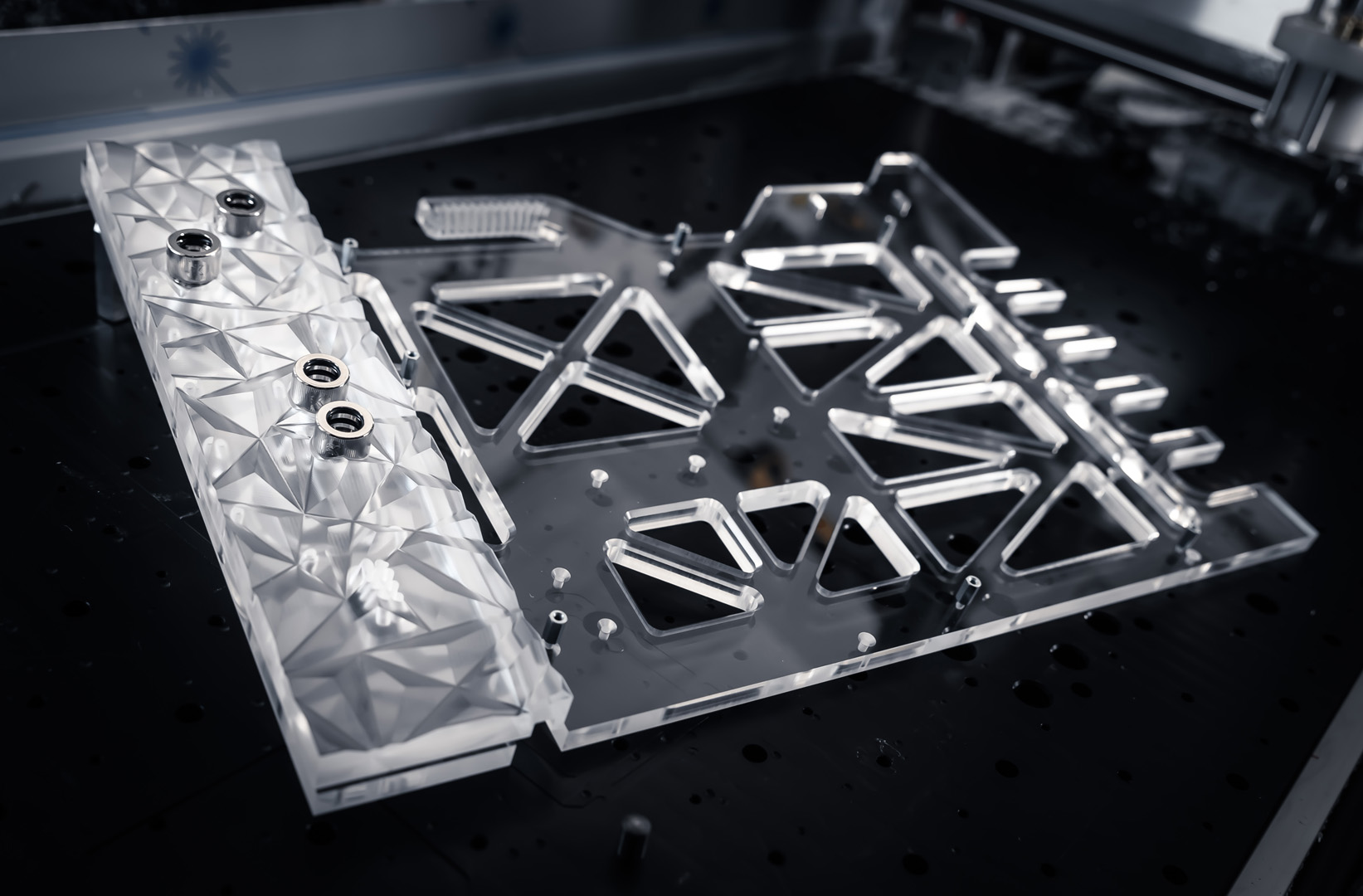
Welcome back to Part 3 of our G.Skill Computex rig project log. In the first part we looked at making a solid aluminium accent piece for the EKWB Velocity CPU water block. In Part 2 we started to manufacture the aluminium portions of the chassis itself. In this section, we’re going to be looking at the acrylic portions of the build, namely the crystalline distro plate and lighting panels!
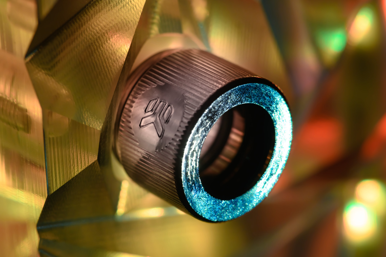
The key feature of the Trident Z Royal RGB design is the crystal light diffuser on the top. Whilst the design might be a bit polarising, it’s definitely unique, and personally I really like it. It therefore seemed like a suitable challenge to try and see if I could replicate this effect in acrylic and add it to the chassis.
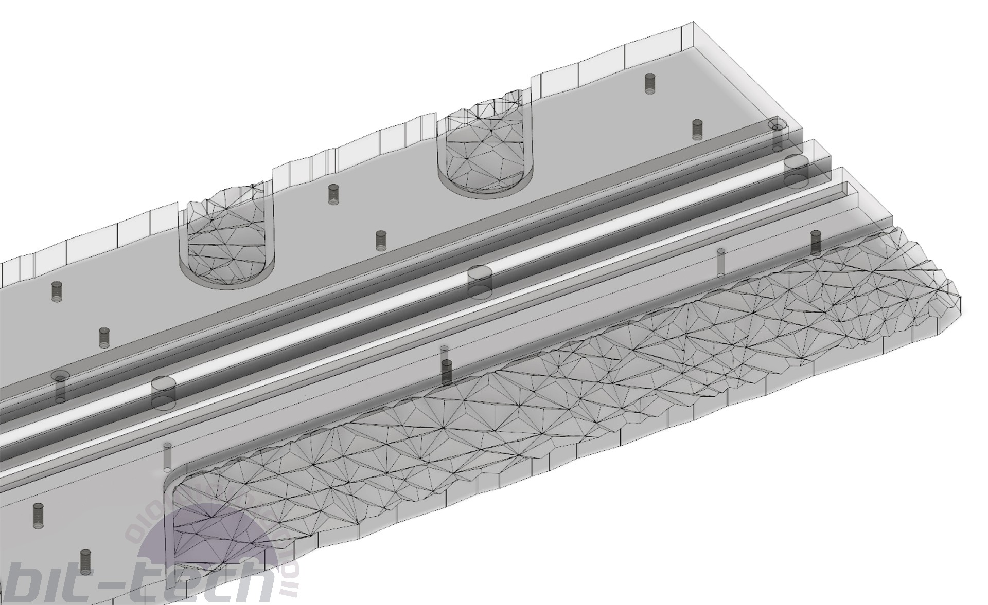
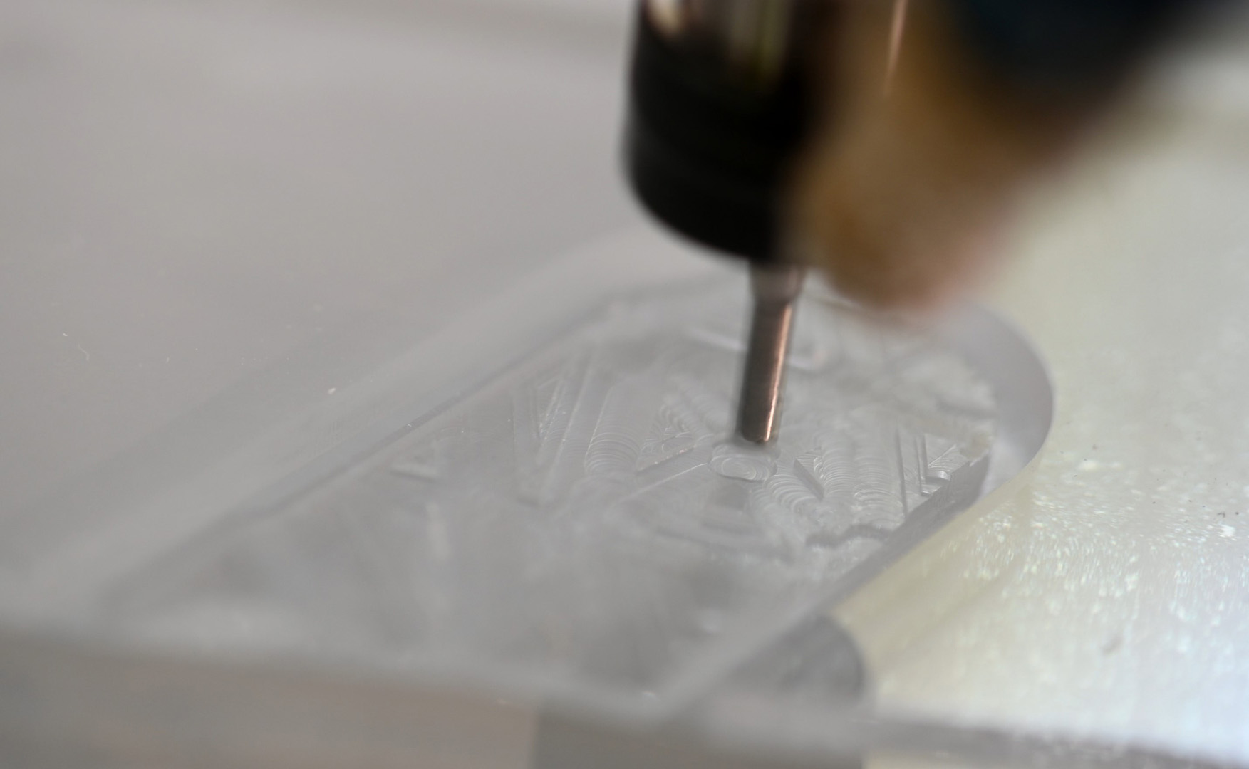
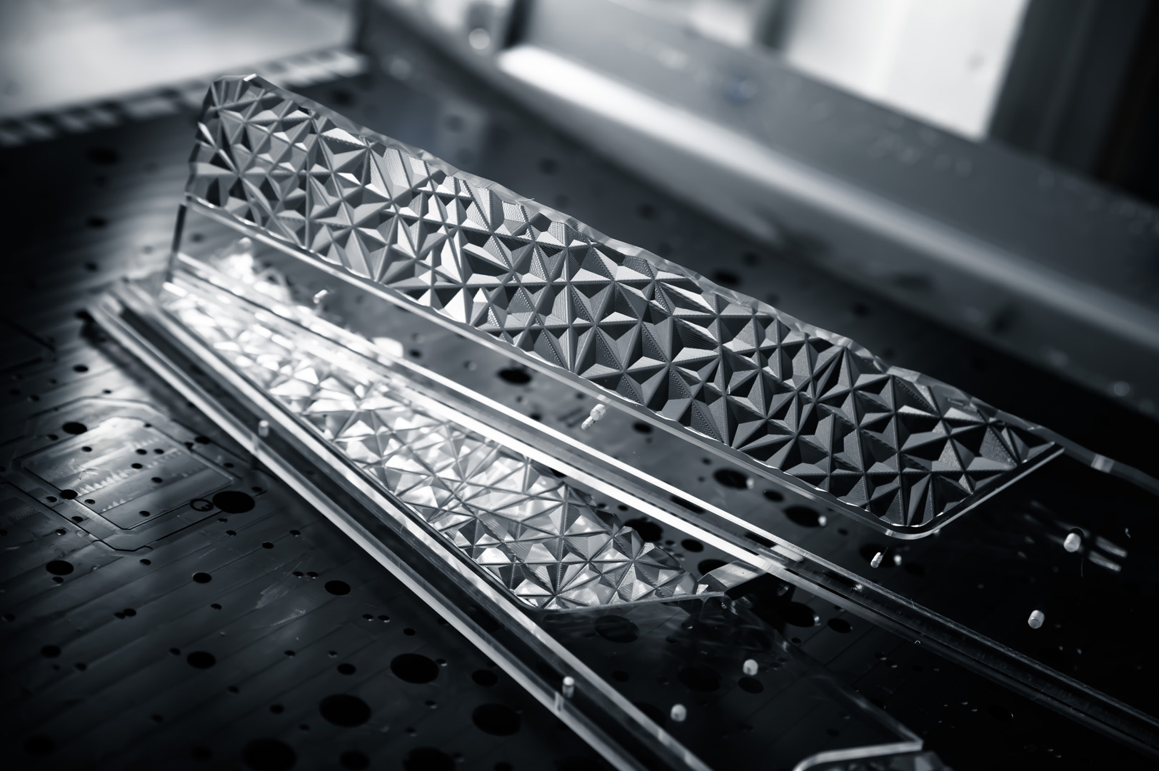
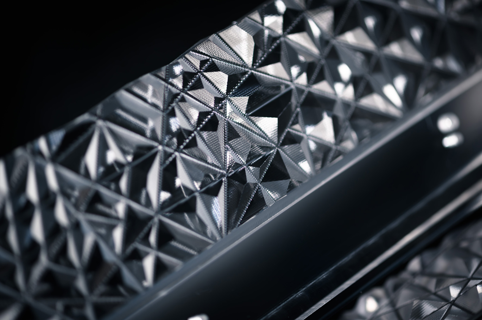
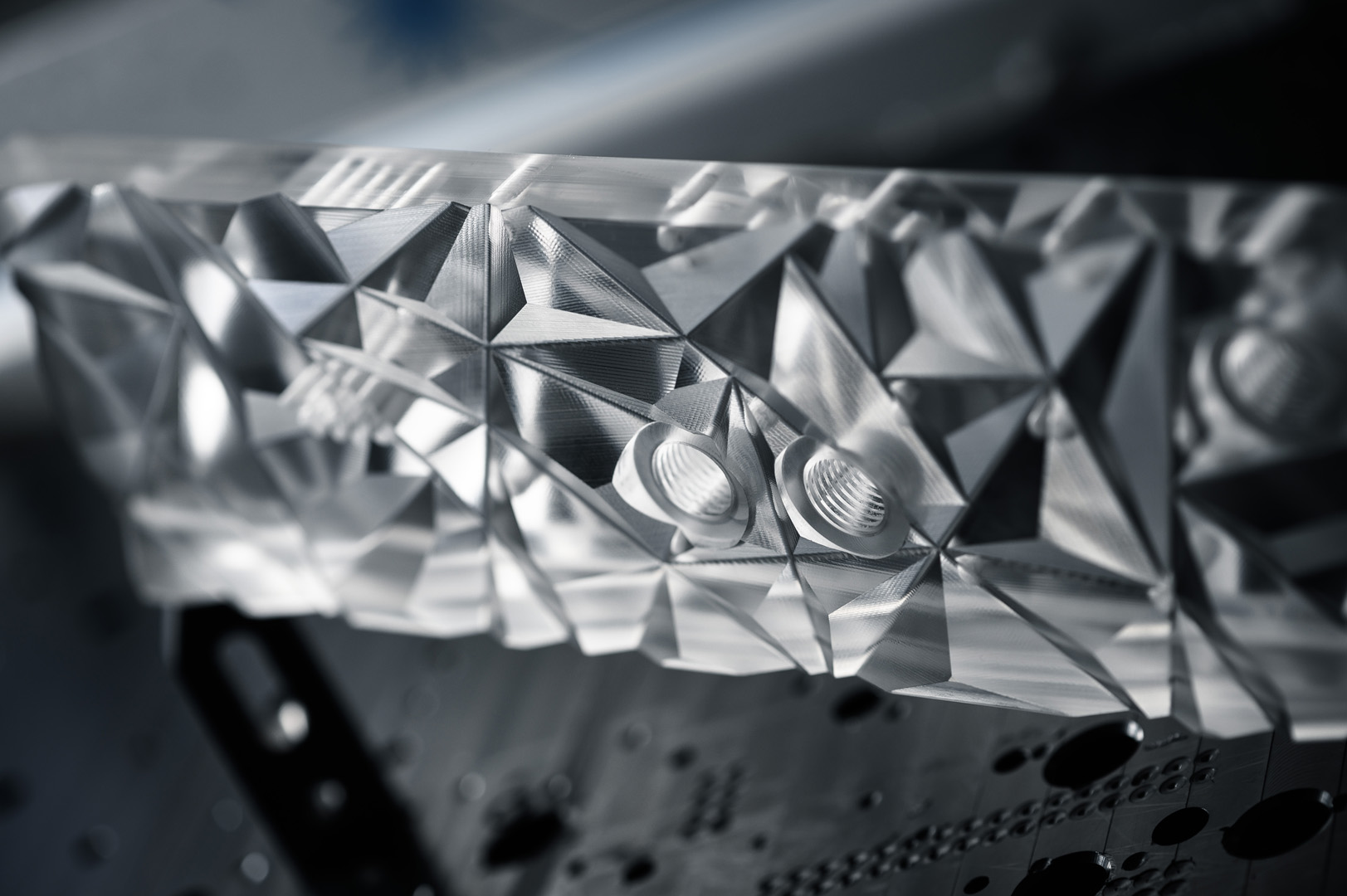
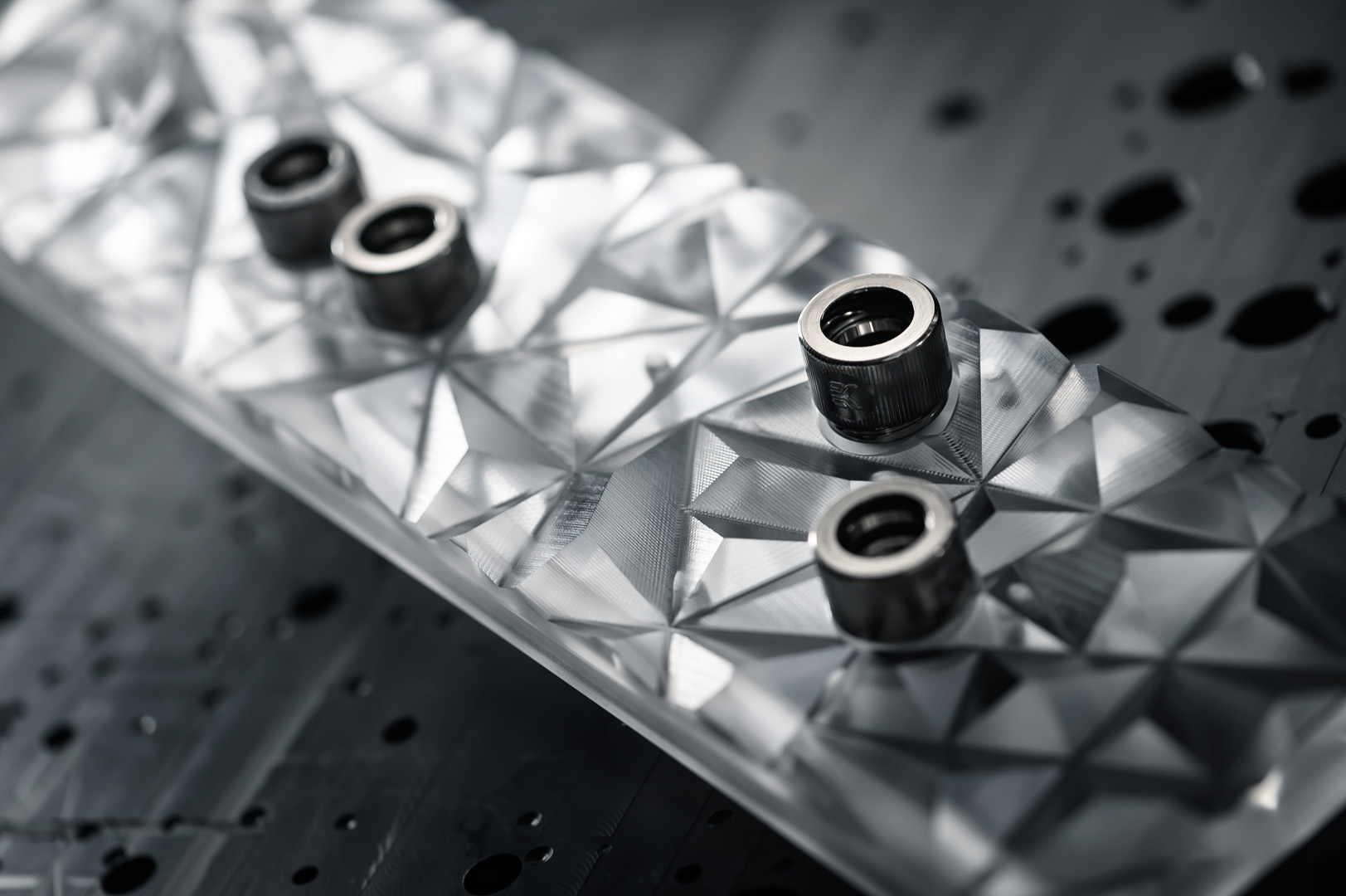
So, how exactly does one produce this particular look? Well, closely inspecting the light diffusers, you can see that rather than being made from internal inclusions, like I had first thought when I saw them last year, they’re moulded polygons. The surface is made from essentially lots of little irregular pyramids.
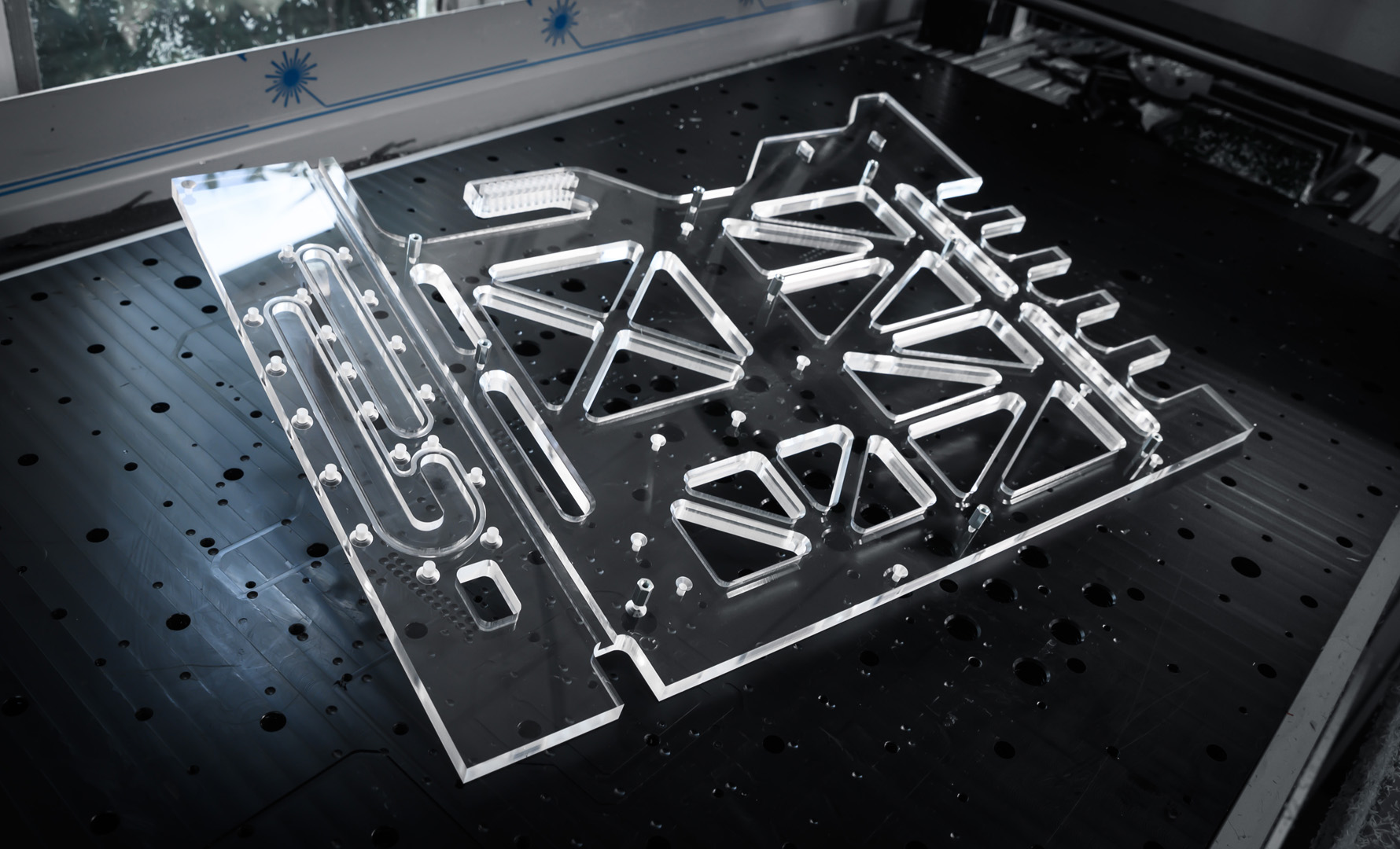
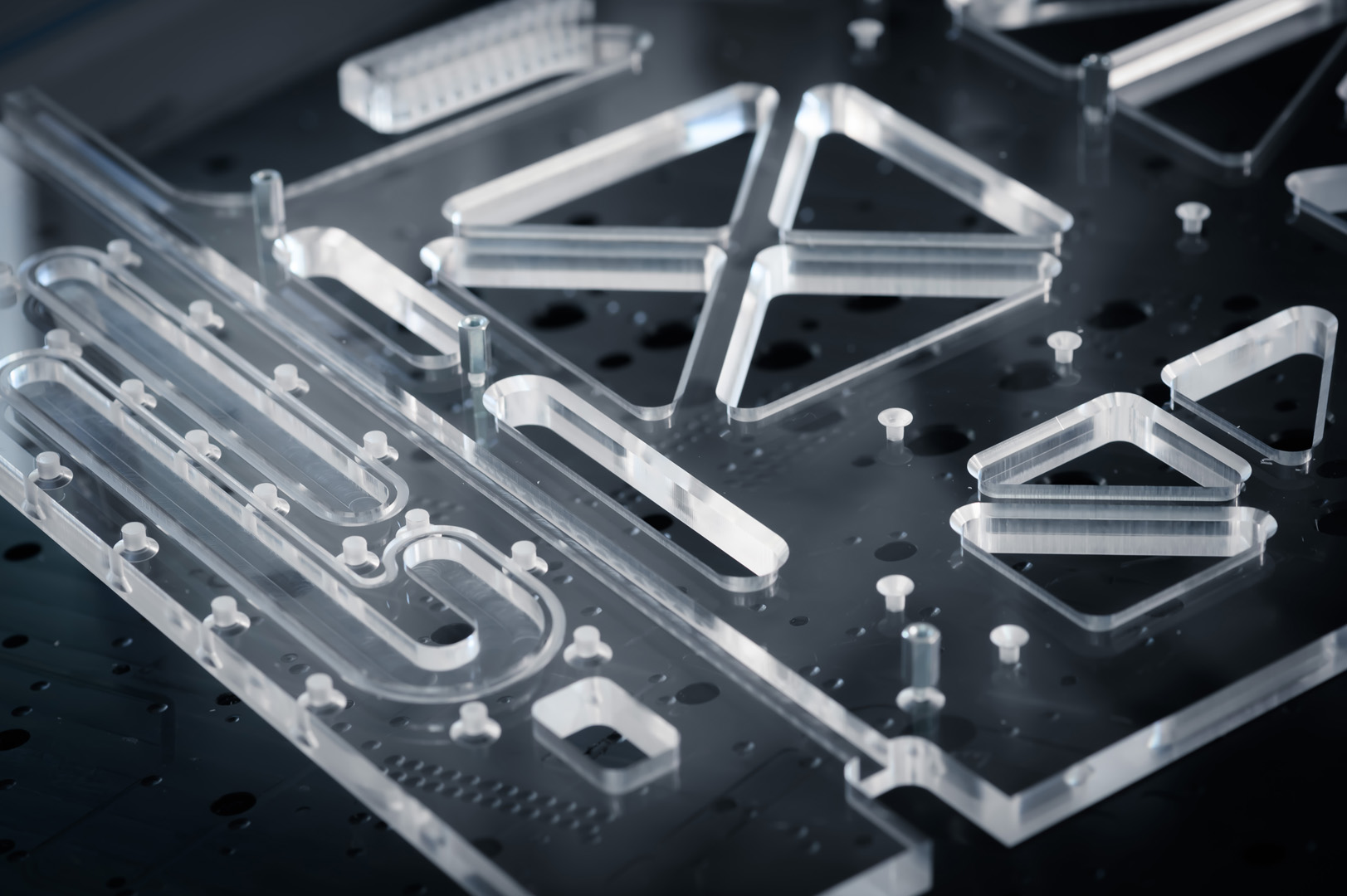
To model this, I went with a fairly simple approach and drew lots of sketch lines across the parts where the crystals would be machined. I then extruded the resulting shapes, using a -60-degree taper to form the pyramids. The effect isn’t 100 percent accurate to the G.Skill stuff, but it’s close enough to match well. For the lighting I simply added in some channels to the edges where LEDs can be slid into place.
Along with the crystals, I also had to focus on the motherboard tray and side distro plate. The side plate is largely unremarkable outside of the fact that it’s fairly tall at 550m. For the pump mount I decided to make an adapter plate rather than put the pump inside the plate directly. This is a process I’m looking to do more often as it means I don’t have to use excessively thick acrylic for entire plates just to accommodate the pump impeller height. If you’re interested in giving this a try yourself, we do have a handy guide on integrating a pump into a distro plate!
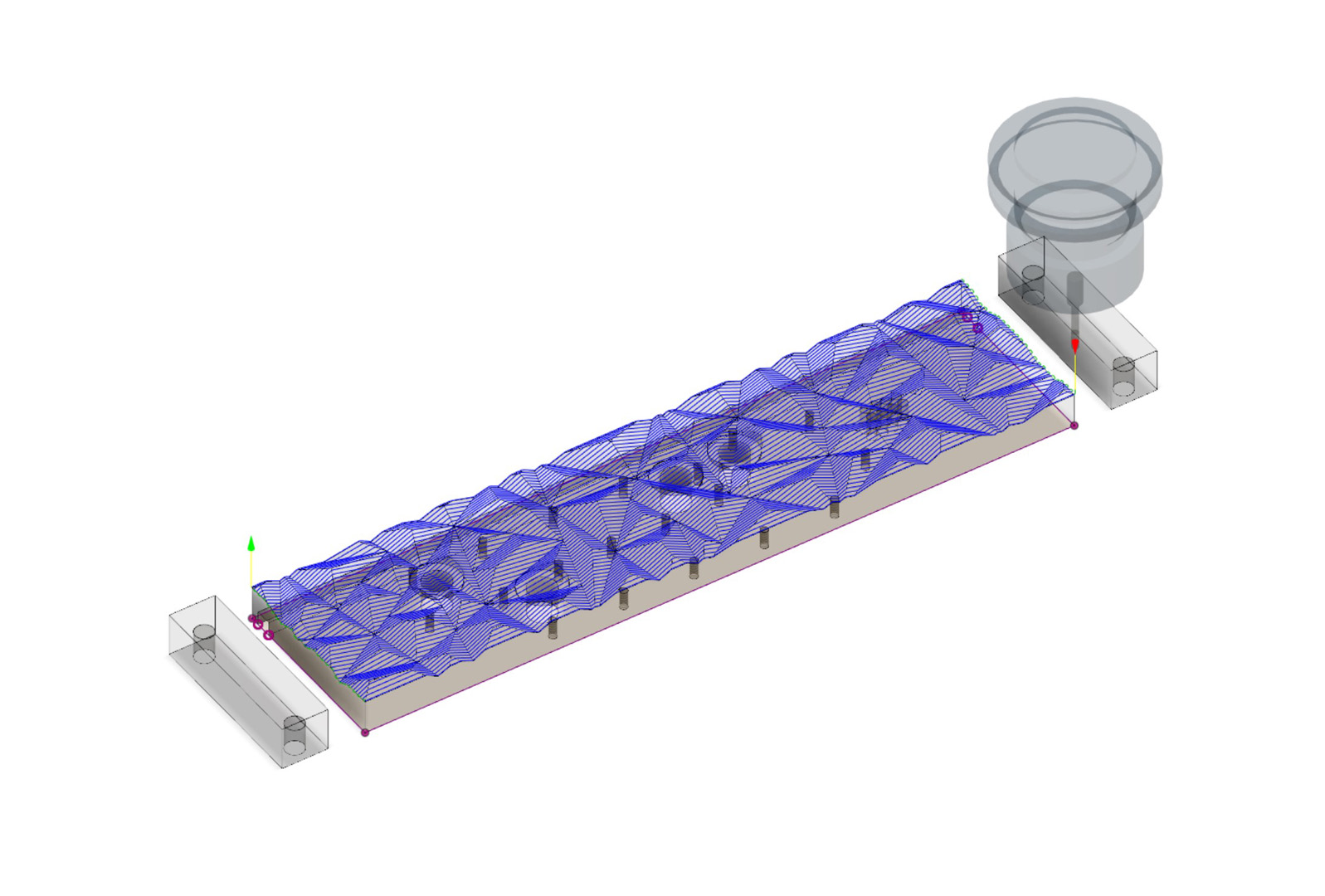
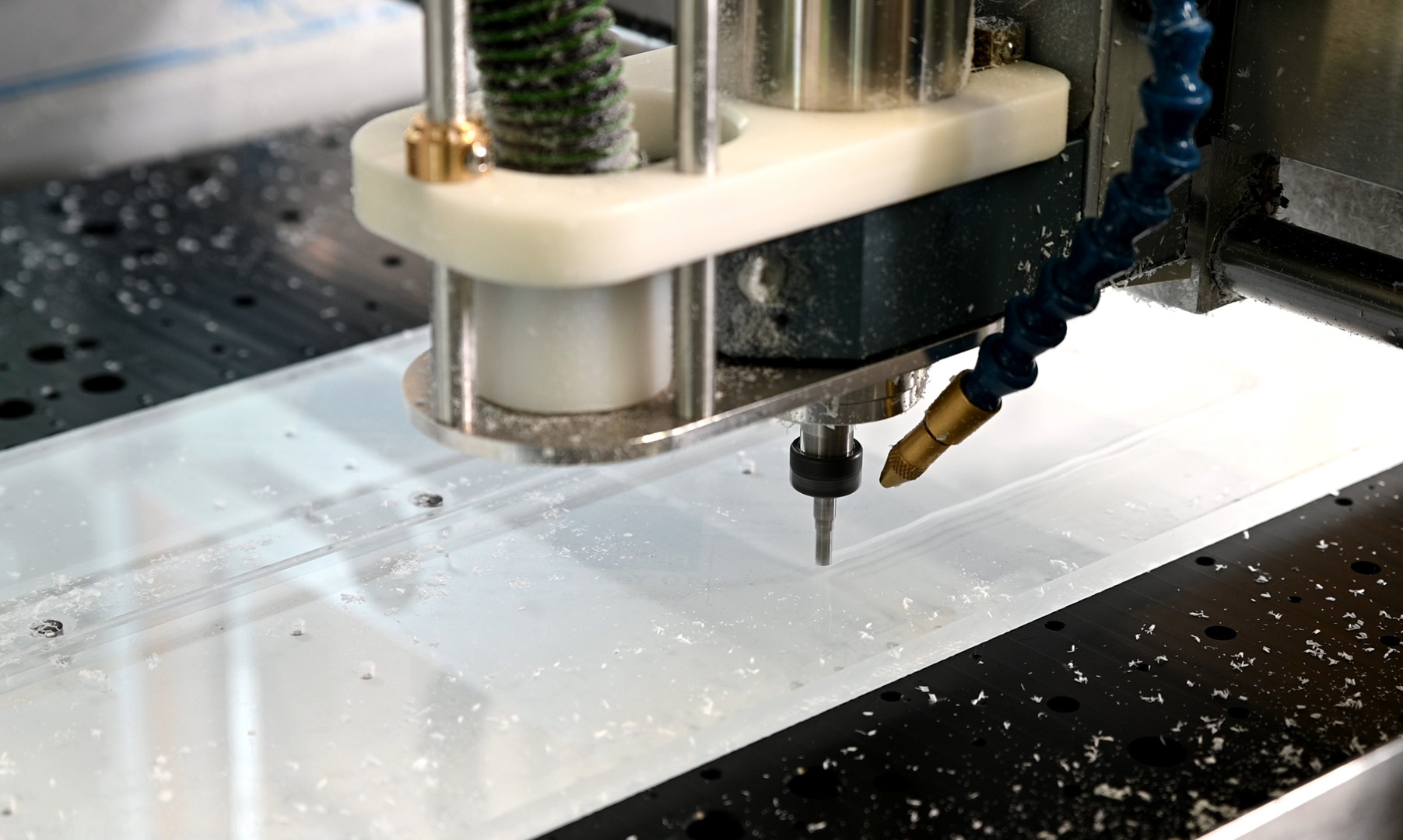
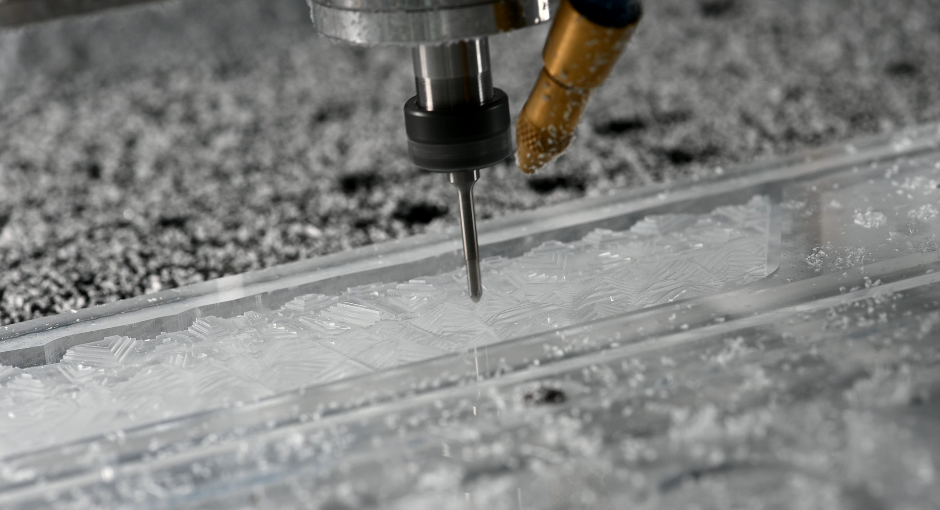
The machining is the real challenge with these parts, and it’s definitely something new for me. To accomplish the 3D milling, I used a 3D adaptive toolpath and a 3mm endmill to rough the work, leaving even 0.5mm step downs. The next toolpath is a 3D parallel paired with a 3mm ball end mill, using a 1.5mm step over. The purpose of this step is to get the main shape properly roughed in so that for the finish pass, the tool will have fairly constant material pressure, which in theory should lead to a better surface finish. For the finish pass I knocked the step over down to 0.2mm. All in all, it was projected to be 6-10 hours of machine time for each of the plates, a wee bit mental compared with my usual cutting jobs.
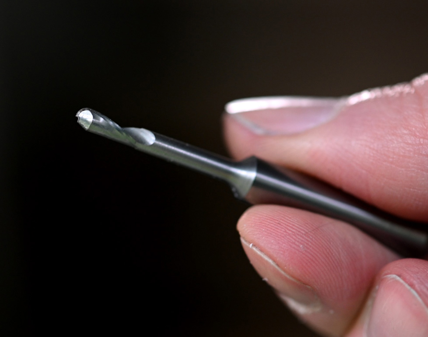
On the bright side, the machining itself went very smoothly. To achieve a smooth finish, I used a Datron 3mm Polished Cut ball end mill, which is specifically designed for cutting acrylic. The key advantage to using the parallel toolpath here is that only two axes are in motion at any given moment. This increases stability and helps the surface finish. I had previously experimented with a similar pattern but using the scallop toolpath. The cutting lines had a great look to them, but you could see in areas where the tool had maybe jogged a little on a corner or surface.
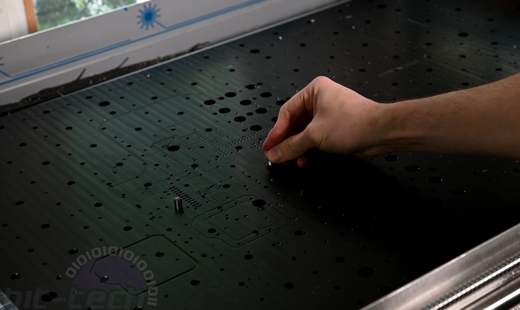
The double-sided milling was handled via the use of dowel pins on my fixture plate. The coordinates for all the features on the plate are saved into my parameters folder. This means I can insert the fixture plate into the toolpathing environment, place parts accurately over the dowel pin locations and have the machine know exactly where it is. This is particularly useful for parts that don’t have any straight edges off which to reference from.
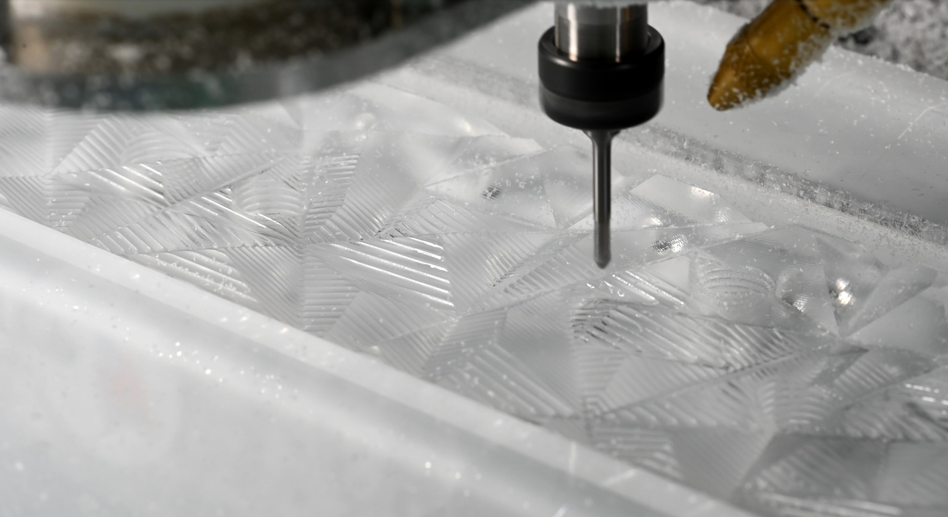
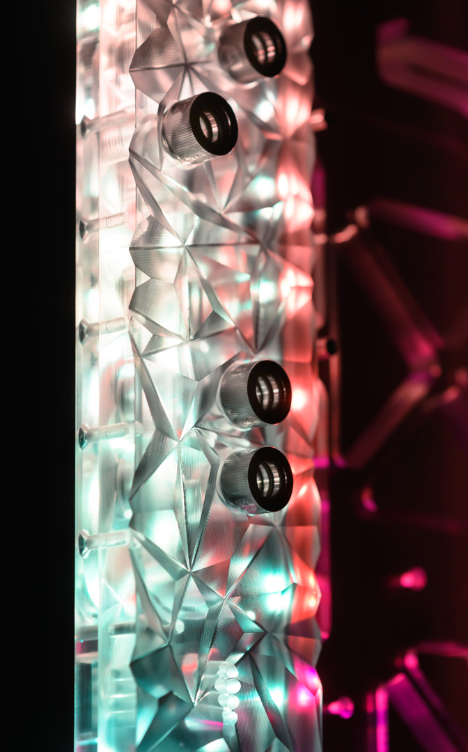
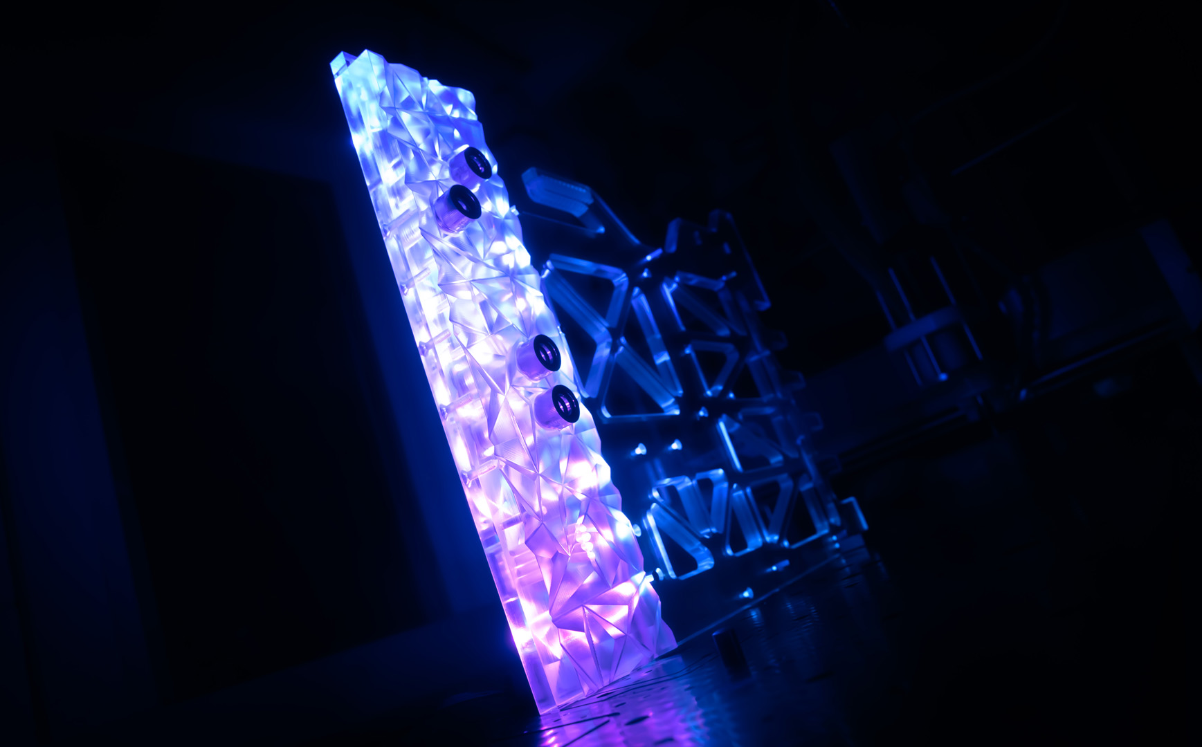
With the pieces cut, I added in the Corsair LEDs and connected it all up to iCUE using a Lighting Node Pro. I’m so pleased with how the effect came out; the light diffuses through the panels much stronger than I was first expecting, I imagine that’s largely down to the faint machining marks. Speaking of which, I decided not to polish them out since the texture really ups the contrast of the piece. I know that the G.Skill ones are very much polished, but they’re also so small that the facets pick up the light regardless. I reckon that had I tried doing the same, the lighting would have been weaker and the crystals far less pronounced (as is what happened with the test piece I mentioned above).
The motherboard tray was tapped to accept 10mm standoffs, and then fitted with a double layer set of LEDS. This arrangement allows one strip to shine upwards and the other downwards, illuminating the back and cables.
Enjoy the eye candy, and I can’t wait to see you in Part 4!
RELATED ARTICLES


MSI MPG Velox 100R Chassis Review
October 14 2021 | 15:04

Want to comment? Please log in.